Appendix
407
Appendix
V
U
8
10
1000
800
1
=
×
=
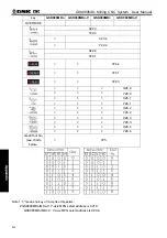
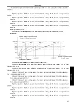
G28.1=1, G28.2=0, at gear-2:
G28.1=0, G28.2=1, at gear-3:
V
U
2
10
4000
800
3
=
×
=
G28.1=1, G28.2=1, at gear-4:
V
U
6
.
1
10
5000
800
4
=
×
=
Output voltage value:
●
S 12-bit code(R12O
~
R01O,F36
~
F37) (R12O2
~
R01O2,F236
~
F237) output:
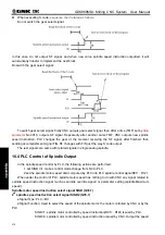
Through the gear shift treatment, NC computes the spindle speed for every gear stage, that is, S 12-bit
code signal R12O
~
R01O(0~4095),R12O2
~
R01O2(0~4095)outputs to spindle frequency converter and
PLC. The relationship between 10V voltage and S 12-bit code is as follow:
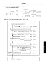
Identified output of S 12-bit code:
That whether S 12-bit code data(R12
O~
R01
O
)(R12
O
2
~
R01
O
2), computed by NC or 12-bit code
input signal(spindle motor speed instruction signalR12I
~
R01I,R12I2
~
R01I2), appointed by PLC, is used
to identify the 1
st
/2
nd
spindle speed instructions decided by SIND/SIND2signal(G33.7/G35.7). When
spindle speed outputted by PLC is chosen, then spindle speed instructions are set by 12-bit code input
signal.
●
voltage offset:
After spindle speed instruction S 12-bit code (0~4095) gotten, data parameterNO.3730 (voltage
compensate value when analog voltage output is 10V) and data parameterNO.3730 (voltage compensate
value when analog voltage output is 0V) can be used to finally compensate and clamp adjustment to
spindle speed instructions. The formula is as follows; take the 1st spindle for example:
9999
4095
036
.
code
bit
-
12
9999
036
.
021
.
9999
output
speed
pindle
×
+
×
−
+
=
NO
S
NO
NO
S
●
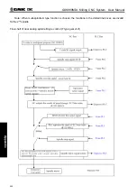
Stop outputting conditions:
When S0 instruction is used, instructions output to spindle are all reset to 0. At this situation, none of
M05, emergency or CNC reset can make spindle speed output instruction of NC reset to 0.
●
analog spindle interface:
V
U
4
10
2000
800
2
=
×
=
Содержание 980MDc
Страница 19: ...GSK980MDc Milling CNC User Manual XVIII ...
Страница 20: ...1 I Programming Programming Ⅰ ...
Страница 21: ...GSK980MDc Milling CNC System User Manual 2 I Programming ...
Страница 139: ...GSK980MDc Milling CNC System User Manual 120 I Programming ...
Страница 191: ...GSK980MDc Milling CNC System User Manual 172 I Programming ...
Страница 192: ...173 Ⅱ Operation Ⅱ Operation ...
Страница 193: ...GSK980MDc Milling CNC System User Manual 174 Ⅱ Operation ...
Страница 200: ...Chapter 1 Operation Mode and Display 181 Ⅱ Operation ...
Страница 201: ...GSK980MDc Milling CNC System User Manual 182 Ⅱ Operation ...
Страница 249: ...GSK980MDc Milling CNC System User Manual 230 Ⅱ Operation ...
Страница 253: ...GSK980MDc Milling CNC System User Manual 234 Ⅱ Operation ...
Страница 259: ...GSK980MDc Milling CNC System User Manual 240 Ⅱ Operation ...
Страница 265: ...GSK980MDc Milling CNC System User Manual 246 Ⅱ Operation ...
Страница 293: ...GSK980MDc Milling CNC System User Manual 274 Ⅱ Operation ...
Страница 295: ...GSK980MDc Milling CNC System User Manual 276 Ⅱ Operation ...
Страница 319: ...GSK980MDc Milling CNC System User Manual 300 Ⅱ Operation ...
Страница 320: ...301 Ⅲ Installation Ⅲ Installation ...
Страница 321: ...GSK980MDc Milling CNC System User Manual 302 Ⅲ Installation ...
Страница 345: ...GSK980MDc Milling CNC System User Manual 326 Ⅲ Installation ...
Страница 391: ...GSK980MDc Milling CNC System User Manual 372 Ⅲ Installation ...
Страница 392: ...Appendix 373 Appendix Appendix ...
Страница 393: ...GSK980MDc Milling CNC System User Manual 374 Appendix ...
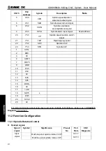
Страница 394: ...Appendix 375 Appendix Appendix 1 Outline Dimension of GSK980MDc L N ...


