SPCP332
SPCP333
PSU (Power Supply Unit) with
Expander
PSU (fuente de alimen-taci6n) con
expansor
PSU (napajeci zdroj) s expanderem
Modut rozszerzenia zasilacza
STEP: A6V10216041, Edition: 18.09.2008
1
2
5
CE
0
6
ill
cJf:
BAT+}11
BAT-
4
3
:
&
�
·
�
·
�
·
7
English
Installation Instruction
&
Before
s
t
a
rt
i
ng to
i
n
s
t
a
ll
a
nd work w
i
th th
is
dev
i
ce, ple
as
e
• re
a
d the S
a
fety In
s
truct
i
o
ns
.
Introduction to the SPCP332/333
11.
B
a
ttery Connector
s
{BAT+, BAT-): 2.5 A fu
s
e
s
SPC PSU Expander
12.
PSU 4-p
i
n Interf
a
ce: Connect
s
to
i
tem 9, Power
a
nd D
a
t
a
The SPCP332/333
a
llow
s
mon
i
tor
i
ng of d
is
tr
i
buted Power
Connector, w
i
th
a s
tr
ai
ght through c
a
ble.
Supply Un
i
t
s
{PSU
s
)
a
nywhere on the SPC X-BUS. The
13.
T
a
mper By-p
ass
[LK1]
Exp
a
nder rece
i
ve
s
power
a
nd d
a
t
a
d
i
rectly from the PSU v
ia a
The jumper
s
ett
i
ng determ
i
ne
s
the operat
i
on of the t
a
mper.
connector c
a
ble
a
nd
i
nterf
a
ce
s
w
i
th the SPC controller v
ia
the
The t
a
mper oper
a
t
i
o
n
c
an
be overr
i
dden by f
i
tt
in
g LK1 _ The
SPC X:BUS: The Exp
a
nder mon
i
tors the PSU for over-current,
eng
i
neer mu
s
t en
s
ure th
a
t LK1
is
removed before le
a
v
i
ng
fu
s
e f
a
il, m
a
in
s
/ AC f
a
il, PSU f
a
il, communic
a
tion
s
f
a
il,
a
nd
si
te for the
s
y
s
tem to comply w
i
th
s
t
a
nd
a
rd
s
.
b
a
ttery p
ro
blem
s
.
.
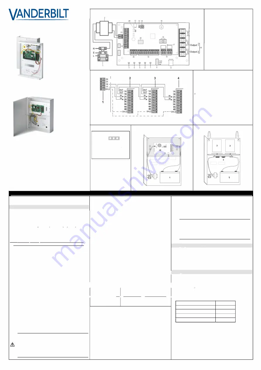
The SPCP332/333
a
nd PSU
i
ncorpor
a
te the follow
i
ng element
s
,
14.
F
ro
nt T
a
mper Switch
.
.
.
as s
hown
i
n
The Exp
a
nder h
as a
front t
a
mper
s
witch with
s
pring. When
F
i
g. 1:
the l
i
d
is
clo
s
ed the
s
pr
in
g clo
s
e
s
the
s
w
i
tch.
I
See Fig:
I
1
I
SPCP332/333 Mounted on PSU
I
15.
Buzzer
Power Supply Unit
1.
M
ai
n
s
Input Block
2. Input Tr
a
n
s
former
3. M
ai
n
s
Power LED {the LED
s
t
a
tu
s is s
hown
i
n Append
i
x A:
LED St
a
tu
s
)
The buzzer
is a
ct
i
v
a
ted
i
n order to loc
a
te the Exp
a
nder {
s
ee
SPC Conf
i
gur
a
t
i
on M
a
nu
a
l). Input
s
: The Exp
a
nder h
as
8 on
bo
a
rd zone
i
nput
s
th
a
t c
an
be conf
i
gured
as i
ntruder
a
l
a
rm
zone
s
on the SPC
s
y
s
tem.
16.
M
a
nu
a
l Addre
ssi
ng Sw
i
tche
s
The
s
w
i
tche
s a
llow m
a
nu
a
l
s
ett
i
ng of the ID of e
a
ch
Expander
i
n the
s
ystem.
23.
PSU T
a
mper Sw
i
tch
a
nd Byp
ass
: Byp
ass
mu
s
t be fitted
i
f
Exp
a
nder
is
mounted on top
a
nd
i
f
i
n
a s
m
a
ll enclo
s
ure.
24.
Term
i
n
a
t
i
on Jumper: Th
is
jumper
as a
def
a
ult
is a
lw
a
y
s
f
i
tted,
however, when w
i
r
i
ng for St
a
r conf
i
gur
a
t
i
on th
is
fitt
in
g
s
hould
be removed. For more
i
nform
a
t
i
on,
s
ee Sect
i
o
n
- W
i
r
in
g the
X-BUS Interf
a
ce.
(I]
When connect
i
ng
a
b
a
ttery to the Power Supply Un
i
t,
en
s
ure th
a
t the po
si
t
i
ve
a
nd neg
a
t
i
ve le
a
d
s a
re
connected to the
i
r re
s
pect
i
ve term
i
n
a
l
s
on the PSU.
En
s
ure th
a
t
a
ll
sa
fety prec
a
ut
i
o
ns a
re
a
dhered to
when h
an
dl
in
g connectors, w
i
re
s
, term
i
n
a
l
s a
nd
PCB
s
.
Charging the Battery Via PSU
Dur
i
ng
n
orm
a
l oper
a
t
i
on, the Power Supply U
ni
t {PSU)
cont
i
nuou
s
ly tr
i
ckle ch
a
rge
s
the b
a
ttery. If the m
ains
power f
ai
l
s
,
the b
a
ttery
s
uppl
i
e
s
power to the PSU output
s
u
n
t
i
l
s
uch t
i
me
as
the b
a
ttery output volt
a
ge d
ro
p
s
to 10.5 V DC {
s
ee Sect
i
o
n
10,
Deep D
is
ch
a
rge Protect
i
on)
a
nd the SPCP332/333
i
n
s
truct
s
the
PSU to tum off.
4.
Fu
s
e F
ai
l LED {the LED
s
t
a
tu
s is s
hown
in
Appe
n
d
i
x A: LED
St
a
tu
s
)
5.
B
a
ttery Ch
a
rge St
a
te LED {the LED
s
t
a
tu
s is s
how
n in
Append
i
x A: LED St
a
tu
s
)
17.
X-BUS St
a
tu
s
LED
�iring the X-BUS interface
The LED
i
nd
i
c
a
te
s
the
s
t
a
tu
s
of the X-BUS when the
s
y
s
tem
.
.
.
6. Curre
n
t L
i
m
i
t LED {the LED
s
t
a
tu
s is s
hown
i
n Append
i
x A:
LED St
a
tu
s
)
7. St
a
tu
s
LED {the LED
s
t
a
tu
s is s
hown
i
n Appe
n
d
i
x A: LED
St
a
tu
s
)
8.
B
a
ttery Selector {the B
a
ttery
s
elector opt
i
on
s a
re
s
hown
i
n
Append
i
x B: L
i
nk Po
si
t
i
on): If the b
a
ttery type
s
elected doe
s
not m
a
tch the b
a
ttery,
i
t w
i
ll c
a
u
s
e the b
a
ttery to ch
a
rge
e
i
ther too
s
lowly,
a
nd not re
a
ch the 80 % c
a
p
a
c
i
ty
i
n the
requ
i
red t
i
me, or too qu
i
ckly, reduc
i
ng the l
i
fe of the b
a
ttery.
The jumper
is
not f
i
tted
as a
def
a
ult, but
is i
n w
i
th the b
a
ttery
le
a
d
s
. The PSU
s
how
s a
f
a
ult
i
f the jumper
is
not f
i
tted.
9.
PSU 4-p
i
n Interf
a
ce: Connect
s
to
i
tem 12, Power
a
nd D
a
t
a
Connector, w
i
th
a s
tr
ai
ght through c
a
ble.
10.
PSU Output
s
{output 1, output 2): E
a
ch output
is
fu
s
ed
s
ep
a
r
a
tely w
i
th elect
roni
c 1 Amp fu
s
e
s
.
CAUTION
The tot
a
l lo
a
d current dr
a
wn f
ro
m output
s
1
a
nd 2
comb
in
ed
s
hould not exceed 1.5 Amp
s
. Th
is is
to
en
s
ure th
a
t enough power
is a
v
ai
l
a
ble to ch
a
rge the
b
a
ttery to 80 % of
i
t
s
norm
a
l c
a
p
a
c
i
ty w
i
th
in
24 hours.
If more power
is
requ
i
red on the
s
y
s
tem, con
si
der
connect
i
ng
a
n
a
dd
i
t
i
on
a
l or h
i
gher rated PSU.
is i
n FULL ENGINEER mode
as s
hown below·
The X-BUS interf
a
ce provide
s
connection of exp
a
nders
a
nd
'
·
keyp
a
d
s
to the SPC Cont
ro
ller. The X-BUS c
a
n be w
i
red
in a
:;::;L:E:D;:::;;s:;;ta:;t:;;u;;:s=======:�D;::e;:s;:c=:ri�o:;:1ti�o::;n=================::::�iq:�:�
0
:n��
e
;:�
t
�
0
s":;�:
a
t��
n
��:
i
:��
i
�T
s
f;n:e:
i
�;,t!1
1
t!��le
Fl
as
he
s
regularly
The X-BUS commun
i
c
a
t
i
o
ns s
t
a
tu
s is
type
s
.
{once every 1.5
OK.
NOTE: M
a
x
i
mum Sy
s
tem c
a
ble length =
n
umber of Exp
an
ders
,>-
s
_e_c _on_d_
s
_
a
�•
P
�
Pro
_ x_.�
l
--t-- - - - -
�- - - - - -
------,
an
d Keyp
a
d
s i
n the
s
y
s
tem x m
a
x
i
mum d
is
t
a
nce for c
a
ble type.
Fl
as
he
s
qu
i
ckly
I
n
d
i
c
a
te
s
e
n
d of l
i
ne exp
a
nder or
{once every 0.2
bre
a
k
i
n exp
a
nders {exclude
s s
t
a
r or
s
econd
s a
pp
ro
x.)
mult
i
-d
ro
p confiour
a
t
i
on
s
)
T
a
b. 1 Techn
i
c
a
l Spec
i
fic
a
t
i
on
18.
Output
s
: The Exp
a
nder prov
i
de
s
two progr
a
mm
a
ble output
s
for u
s
e on the SPC
s
y
s
tem.
19.
Input
s
: The Exp
a
nder h
as
8 on-bo
a
rd zone
i
nput
s
th
a
t c
a
n
be configured
as i
ntruder
a
l
a
rm zo
n
e
s
on the SPC
s
y
s
tem
{
s
ee Sect
i
on - W
i
r
i
ng the Input
s
).
20.
Aux
i
l
ia
ry Power Supply (12 V): The
s
e
a
re u
s
ed to power
a
ux
i
l
ia
ry dev
i
ce
s
to
a
m
a
x
i
mum of 200 mA,
s
ubject to the
1.5 A m
a
x
i
mum l
i
m
i
t on the SPC PSU m
ai
n
s s
upply.
21.
Input Power: No
i
nput power
is
requ
i
red
i
f Exp
an
der
is
connected to PSU
22.
X-BUS Interf
a
ce: The commun
i
c
a
t
i
on
s
bu
s
connect
s
Exp
a
nder
s
on the SPC
s
y
s
tem.
Cable Type
Distance
CQR
s
t
a
nd
a
rd
a
l
a
rm c
a
ble
200 m
UTP C
a
tegory: 5 {
s
ol
i
d core) 400 m
Belden 9829
400 m
IYSTY 2 x 2 x 0.6 {m
i
n)
400 m
T
a
b. 2 C
a
ble Type
s a
nd D
is
t
a
nce
s


