GSK980MDc Milling CNC System User Manual
358
Ⅲ
Inst
allation
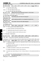
Data parameter
№
5261
:
Linear acceleration/deceleration time constant in rigid tapping tool infeed;
Data parameter
№
5271
:
Linear acceleration/deceleration time constant in rigid tapping tool retraction;
Data parameter
№
5211
:
Override value in rigid tapping tool retract;
Data parameter
№
025
:
Feedrate of DRY run;
SMZ of bit parameter
№
007: for validity of smoothing transition between blocks
The larger the acceleration & deceleration time constant is, the slower acceleration &
deceleration is, the smaller the machine movement impact and the lower the machining efficiency is.
And vice versa.
If acceleration & deceleration time constants are equal, the higher the acceleration & deceleration
start/end speed is, the faster the acceleration & deceleration is, the bigger the machine movement impact
and the higher the machining efficiency is, and vice versa.
The principle for acceleration & deceleration
characteristic adjustment is to properly
reduce
the acceleration & deceleration time constant and increase the acceleration & deceleration start/end speed
to improve the machining efficiency on the condition that there is no alarm, motor out-of-step and obvious
machine impact. If the acceleration & deceleration time constant is set too small, and the start/end speed is
set too large, it is easily to cause drive unit alarm, motor out-of-step or machine vibration.
When the bit parameter
№
007 BIT3
(
SMZ
)
=1, the feedrate drops to the start speed of the
acceleration & deceleration at the cutting path intersection, then it accelerates to the specified speed of the
adjacent block to obtain an accurate positioning at the path intersection, but this will reduce the machining
efficiency. When SMZ=0, the adjacent cutting path transits smoothly by the acceleration & deceleration.
The feedrate does not always drop to the start speed when the previous path is finished and a circular
transition (non-accurate positioning) will be formed at the path intersection. The machining surface
by this path transition has a good finish and a higher machining efficiency. When the
stepper motor drive unit is applied, the SMZ of the bit parameter
№
007 should be set to 1 to avoid the
out-of-step.
When the stepper motor drive unit is applied to this system, the out-of-step may occur if rapid traverse
speed is too large, acceleration & deceleration time constant is too small, acceleration & deceleration
start/end speed is too large. The suggested parameter setting is shown in follows (the electronic gear
ratio is 1:1):
Data parameter
№
022
≤
5000 Data parameter
№
023
≥
350 Data parameter
№
030
≤
50
Data parameter
№
029
≥
150 Data parameter
№
041
≤
50 Data parameter
№
042
≥
150
When AC servo motor drive unit is applied to this system, the machining efficiency can be improved by
a larger start speed and smaller ACC&DEC time constant setting. If optimum ACC&DEC characteristics are
required, the ACC&DEC time constant may be set to 0
,
which can be got by adjusting the AC servo
ACC&DEC parameters. The suggested parameter settings are as follows (electronic gear ratio is 1:1).
Data parameter
№
022 set higher properly
Data parameter
№
023
≤
60
Data parameter
№
030
≥
50
Data parameter
№
029
≤
50
Data parameter
№
041
≥
50
Data parameter
№
042
≤
50
The parameter settings above are recommended for use, refer to the actual conditions of the drive unit,
motor characteristic and machine load for its proper setting.
4.5 Machine Zero Adjustment
Adjust the relevant parameters based on the valid level of the connection signal, zero return type or
Содержание 980MDc
Страница 19: ...GSK980MDc Milling CNC User Manual XVIII ...
Страница 20: ...1 I Programming Programming Ⅰ ...
Страница 21: ...GSK980MDc Milling CNC System User Manual 2 I Programming ...
Страница 139: ...GSK980MDc Milling CNC System User Manual 120 I Programming ...
Страница 191: ...GSK980MDc Milling CNC System User Manual 172 I Programming ...
Страница 192: ...173 Ⅱ Operation Ⅱ Operation ...
Страница 193: ...GSK980MDc Milling CNC System User Manual 174 Ⅱ Operation ...
Страница 200: ...Chapter 1 Operation Mode and Display 181 Ⅱ Operation ...
Страница 201: ...GSK980MDc Milling CNC System User Manual 182 Ⅱ Operation ...
Страница 249: ...GSK980MDc Milling CNC System User Manual 230 Ⅱ Operation ...
Страница 253: ...GSK980MDc Milling CNC System User Manual 234 Ⅱ Operation ...
Страница 259: ...GSK980MDc Milling CNC System User Manual 240 Ⅱ Operation ...
Страница 265: ...GSK980MDc Milling CNC System User Manual 246 Ⅱ Operation ...
Страница 293: ...GSK980MDc Milling CNC System User Manual 274 Ⅱ Operation ...
Страница 295: ...GSK980MDc Milling CNC System User Manual 276 Ⅱ Operation ...
Страница 319: ...GSK980MDc Milling CNC System User Manual 300 Ⅱ Operation ...
Страница 320: ...301 Ⅲ Installation Ⅲ Installation ...
Страница 321: ...GSK980MDc Milling CNC System User Manual 302 Ⅲ Installation ...
Страница 345: ...GSK980MDc Milling CNC System User Manual 326 Ⅲ Installation ...
Страница 391: ...GSK980MDc Milling CNC System User Manual 372 Ⅲ Installation ...
Страница 392: ...Appendix 373 Appendix Appendix ...
Страница 393: ...GSK980MDc Milling CNC System User Manual 374 Appendix ...
Страница 394: ...Appendix 375 Appendix Appendix 1 Outline Dimension of GSK980MDc L N ...

