GSK980MDc Milling CNC System User Manual
118
I Programming
3.30.7 F and G Signals
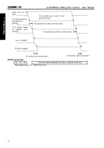
RGTAP (G61.0): Rigid tapping signal
When the M 29 is commanded, PMC enters the rigid tapping mode, and the signal is then set to 1 to
inform the CNC
1: PMC enters the rigid tapping mode
0: PMC does not enter the rigid tapping mode
If this signal does not set to 1, after the M29 has been commanded, the alarm may occur in the block of
G74/G84.
RGSPM, RGSPP (F65.1, 0) spindle turning signal
When the rigid tapping is performed, the signal is informed to the PMC whether the current spindle is
CCW (positive) or CW (negative).
RGSPM: 1 spindle CW (negative) RGSPP: 1 spindle CCW (positive)
In rigid tapping, these signals are output when the spindle is rotated. In the mode of rigid tapping, when
the spindle is positioned at the hole or stopped at the bottom of the hole or R position, these signals are not
output.
In the mode of rigid tapping, when the spindle is positioned at the inter-locked stop, machine lock or Z
axis ignorance states, the spindle does not regard as a stop state, in this case, these signals are output.
These signals are only enabled in rigid tapping, and they are all set to 0 in the normal spindle control mode.
RTAP (F76.3): Rigid tapping process signal
This signal informs PMC which has been in the mode of rigid tapping or not. The CNC is in the mode of
rigid tapping currently when the signal is set to 1.
This signal can be locked M29, PLC has been commanded the rigid tapping mode, the PMC is then
treated with the corresponding logic, and this signal can be replaced the lock of M29, even so, the FIN
signal of M29 is not ignored still.
3.30.8 Alarm Message
Alarm
No.
Display Content
Explanation
218 Fail to specify the tool pitch F value in G74 or G84 Fail to specify F value
230 The spindle feed can not be performed due to the
S value is 0.
S value is 0, or S code does not specify.
231 S value exceeds the maximum spindle speed
allowed with rigid tapping
S value exceeds the setting value of data
parameter 086
232 Other axis movement codes are specified
between M29 and G74/G84.
Specify a axis movement between M29
and G74/G84
233 G61.0 signal is abnormal in rigid tapping mode
Rigid tapping signal G61.0 is not 1 during
performing in G74/G84.
234 Specify
M29
repeatedly
Specify M29 or it is consecutively
specified more than twice in rigid tapping.
Содержание 980MDc
Страница 19: ...GSK980MDc Milling CNC User Manual XVIII ...
Страница 20: ...1 I Programming Programming Ⅰ ...
Страница 21: ...GSK980MDc Milling CNC System User Manual 2 I Programming ...
Страница 139: ...GSK980MDc Milling CNC System User Manual 120 I Programming ...
Страница 191: ...GSK980MDc Milling CNC System User Manual 172 I Programming ...
Страница 192: ...173 Ⅱ Operation Ⅱ Operation ...
Страница 193: ...GSK980MDc Milling CNC System User Manual 174 Ⅱ Operation ...
Страница 200: ...Chapter 1 Operation Mode and Display 181 Ⅱ Operation ...
Страница 201: ...GSK980MDc Milling CNC System User Manual 182 Ⅱ Operation ...
Страница 249: ...GSK980MDc Milling CNC System User Manual 230 Ⅱ Operation ...
Страница 253: ...GSK980MDc Milling CNC System User Manual 234 Ⅱ Operation ...
Страница 259: ...GSK980MDc Milling CNC System User Manual 240 Ⅱ Operation ...
Страница 265: ...GSK980MDc Milling CNC System User Manual 246 Ⅱ Operation ...
Страница 293: ...GSK980MDc Milling CNC System User Manual 274 Ⅱ Operation ...
Страница 295: ...GSK980MDc Milling CNC System User Manual 276 Ⅱ Operation ...
Страница 319: ...GSK980MDc Milling CNC System User Manual 300 Ⅱ Operation ...
Страница 320: ...301 Ⅲ Installation Ⅲ Installation ...
Страница 321: ...GSK980MDc Milling CNC System User Manual 302 Ⅲ Installation ...
Страница 345: ...GSK980MDc Milling CNC System User Manual 326 Ⅲ Installation ...
Страница 391: ...GSK980MDc Milling CNC System User Manual 372 Ⅲ Installation ...
Страница 392: ...Appendix 373 Appendix Appendix ...
Страница 393: ...GSK980MDc Milling CNC System User Manual 374 Appendix ...
Страница 394: ...Appendix 375 Appendix Appendix 1 Outline Dimension of GSK980MDc L N ...

