GSK980MDc Milling CNC System User Manual
410
Appendix
z
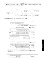
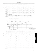
When executing S code,
sequence chart related as follows:
Do not switch the gear select signal:
In this case, do not output SF signal, and when new value spindle speed instruction outputted, it will
automatically transfer to implement the next block.
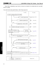
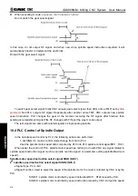
Do switch the gear select signal:
To switch gear select signal, firstly CNC outputs gear select signal, then after a time (TMF) set by
data
parameter
No.3010, outputs SF signal. Repeatedly after another same TMF, CNC outputs new spindle
speed instruction. PLC changes the gear at the moment receiving the SF signal, after finished, then
sending accomplishment signal FIN. SF changes with FIN just the way S code output.
The rest signals are same with related signals in single analog spindle.
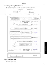
10.4 PLC Control of Spindle Output
In the spindle speed control by PLC, the following actions are performed:
1: set SIND to1, makes control mode change from NC to PLC.
2:set the spindle motor speed data computed by PLC into PLC spindle control signalR01I
~
R12I.
When under the control of PLC, spindle motor speed has nothing to do with CNC any signal related to
spindle speed instruction signal (such as spindle override signal) or parameter setting (spindle Maximum
speed).
Spindle motor speed instruction select signal SIND (G33.7)
2
nd
spindle speed instruction select signal SIND2 (G35.7)
●
Signal Type: PLC
→
NC
●
Signal Function: Used to select the speed of the spindle motor; the motor controlled by CNC or by the
PLC.
SIND=1: spindle motor controlled by speed instruction(R01I
~
R12I) issued by PLC.
SIND=0: spindle motor controlled by speed instruction issued by CNC. Output the speed
Содержание 980MDc
Страница 19: ...GSK980MDc Milling CNC User Manual XVIII ...
Страница 20: ...1 I Programming Programming Ⅰ ...
Страница 21: ...GSK980MDc Milling CNC System User Manual 2 I Programming ...
Страница 139: ...GSK980MDc Milling CNC System User Manual 120 I Programming ...
Страница 191: ...GSK980MDc Milling CNC System User Manual 172 I Programming ...
Страница 192: ...173 Ⅱ Operation Ⅱ Operation ...
Страница 193: ...GSK980MDc Milling CNC System User Manual 174 Ⅱ Operation ...
Страница 200: ...Chapter 1 Operation Mode and Display 181 Ⅱ Operation ...
Страница 201: ...GSK980MDc Milling CNC System User Manual 182 Ⅱ Operation ...
Страница 249: ...GSK980MDc Milling CNC System User Manual 230 Ⅱ Operation ...
Страница 253: ...GSK980MDc Milling CNC System User Manual 234 Ⅱ Operation ...
Страница 259: ...GSK980MDc Milling CNC System User Manual 240 Ⅱ Operation ...
Страница 265: ...GSK980MDc Milling CNC System User Manual 246 Ⅱ Operation ...
Страница 293: ...GSK980MDc Milling CNC System User Manual 274 Ⅱ Operation ...
Страница 295: ...GSK980MDc Milling CNC System User Manual 276 Ⅱ Operation ...
Страница 319: ...GSK980MDc Milling CNC System User Manual 300 Ⅱ Operation ...
Страница 320: ...301 Ⅲ Installation Ⅲ Installation ...
Страница 321: ...GSK980MDc Milling CNC System User Manual 302 Ⅲ Installation ...
Страница 345: ...GSK980MDc Milling CNC System User Manual 326 Ⅲ Installation ...
Страница 391: ...GSK980MDc Milling CNC System User Manual 372 Ⅲ Installation ...
Страница 392: ...Appendix 373 Appendix Appendix ...
Страница 393: ...GSK980MDc Milling CNC System User Manual 374 Appendix ...
Страница 394: ...Appendix 375 Appendix Appendix 1 Outline Dimension of GSK980MDc L N ...


