GSK980MDc Milling CNC System User Manual
424
Appendix
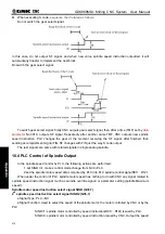
holding time.
z
Control logic
SSTP output is valid after the CNC power on. M03 or M04 is executed when SSTP output is valid.
When SFR or SRV output is valid and held on, SSTP output is stopped at the same time. M05 is executed
when SFR or SRV is valid. When SFR or SRV is stopped, SSTP output is valid and held. Spindle brake
SPZD signal output delay time is set by PLC data DT022 (the delay time between spindle stop commands
output to spindle brake SPZD signal output). The holding time of brake signal is set by PLC data DT023
(spindle brake output time).
If the current spindle is in the state of CCW/CW rotation, PLC alarm A0.3 (M03, M04 specify the error)
occurs when M04 or M03 is executed.
Note 1: When the CNC external stop or spindle alarm, the spindle rotation signal is stopped and SSTP signal is
output at the same time.
Note 2: In CNC reset, RSJG of K0010 of the PLC set whether cancel SFR, SRV output.
When RSJG
=
0, CNC reset to stop SFR, SRV output.
When RSJG
=
1, CNC reset SFR, SRV output state is unchanged.
Note 3: 436 alarm occurs (spindle alarm) after the APAL signal is detected by the CNC, and F35.0 is 1.
Note 4: In spindle analog quantity control, spindle enable signal is valid when output voltage is greater than 0.
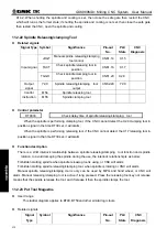
11.2.2 The 2
nd
spindle rotation control
z
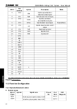
Related signals
Signal
type
Signal
symbol
Significance
Pin-out
No.
PLC
State
CNC
Diagnosis
Spindle CW key of the 2
nd
spindle
machine panel
X21.7
Spindle CCW key of the 2
nd
spindle
machine panel
X21.3
Input
signal
The
2
nd
spindle machine panel stop
key
X21.5
SRV2
CCW signal of the 2
nd
spindle
CN62.41
Y3.4
SFR2
signal of the 2
nd
spindle
CN62.40
Y3.3
Output
signal
SPZD
Breaking signal of the 2
nd
spindle CN62.42
Y3.5
M73
CW instruction signal of the 2
nd
spindle
M74
CW instruction signal of the 2
nd
spindle
Instruction
input
M75
Stop instruction signal of the 2
nd
spindle
Note: for the 1
st
spindle relative signals, please see to spindle rotation control description.
z
Parameter control
Содержание 980MDc
Страница 19: ...GSK980MDc Milling CNC User Manual XVIII ...
Страница 20: ...1 I Programming Programming Ⅰ ...
Страница 21: ...GSK980MDc Milling CNC System User Manual 2 I Programming ...
Страница 139: ...GSK980MDc Milling CNC System User Manual 120 I Programming ...
Страница 191: ...GSK980MDc Milling CNC System User Manual 172 I Programming ...
Страница 192: ...173 Ⅱ Operation Ⅱ Operation ...
Страница 193: ...GSK980MDc Milling CNC System User Manual 174 Ⅱ Operation ...
Страница 200: ...Chapter 1 Operation Mode and Display 181 Ⅱ Operation ...
Страница 201: ...GSK980MDc Milling CNC System User Manual 182 Ⅱ Operation ...
Страница 249: ...GSK980MDc Milling CNC System User Manual 230 Ⅱ Operation ...
Страница 253: ...GSK980MDc Milling CNC System User Manual 234 Ⅱ Operation ...
Страница 259: ...GSK980MDc Milling CNC System User Manual 240 Ⅱ Operation ...
Страница 265: ...GSK980MDc Milling CNC System User Manual 246 Ⅱ Operation ...
Страница 293: ...GSK980MDc Milling CNC System User Manual 274 Ⅱ Operation ...
Страница 295: ...GSK980MDc Milling CNC System User Manual 276 Ⅱ Operation ...
Страница 319: ...GSK980MDc Milling CNC System User Manual 300 Ⅱ Operation ...
Страница 320: ...301 Ⅲ Installation Ⅲ Installation ...
Страница 321: ...GSK980MDc Milling CNC System User Manual 302 Ⅲ Installation ...
Страница 345: ...GSK980MDc Milling CNC System User Manual 326 Ⅲ Installation ...
Страница 391: ...GSK980MDc Milling CNC System User Manual 372 Ⅲ Installation ...
Страница 392: ...Appendix 373 Appendix Appendix ...
Страница 393: ...GSK980MDc Milling CNC System User Manual 374 Appendix ...
Страница 394: ...Appendix 375 Appendix Appendix 1 Outline Dimension of GSK980MDc L N ...

