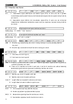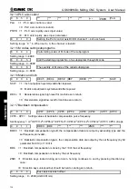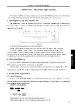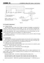
Chapter 5 Diagnosis Message
365
Ⅲ
Inst
allation
0
0 8
2
As power off,5th start position of executing segment
0 0 8 3
When the power off, G mode of group 01
(
G00~G03,G73~G139
)
0 0 8 4
When the power off, G mode of group 02(G17
~
G19)
0
0 8
5
When the power off, G mode of group 03(G90, G91)
0
0 8
6
When the power off, G mode of group 05(G94, G95)
0
0 8
7
When the power off, G mode of group 06(G20, G21)
0 0 8 8
When the power off, G mode of group 07(G40
~
G42)
0
0 8
9
When the power off, G mode of group 08(G43/44/49)
0
0 9
0
When the power off, G mode of group10(G98, G99)
0
0 9
1
When the power off, G mode of group11(G50, G51)
0
0 9
2
When the power off, G mode of group12(G66~G67)
0 0 9 3
When the power off, G mode of group14(G54
~
G59)
0
0 9
4
When the power off, G mode of group16(G68~G69)
0
0 9
5
When the power off, G mode of group17(G15~G16)
0
0 9
6
When the power off, G mode of group22 (G50.1, G51.1)_X axis
0
0 9
7
When the power off, G mode of group22 (G50.1, G51.1)_Y axis
0
0 9
8
When the power off, G mode of group22 (G50.1, G51.1)_Z axis
0
0 9
9
The value of F when the power off.
0
1 0
0
The value of S when the power off.
0
1 0
1
The value of H when the power off.
0
1 0
2
The value of D when the power off.
0
1 0
7
Counts of X pulse from checking PC to receiving PC in Ref.
0
1 0
8
Counts of Y pulse from checking PC to receiving PC in Ref.
0
1 0
9
Counts of Z pulse from checking PC to receiving PC in Ref.
0
1 1
0
Counts of 4th pulse from checking PC to receiving PC in Ref.
0
1 1
1
Counts of 5th pulse from checking PC to receiving PC in Ref.
0
1 1
2
The pulse counts of spindle encoder
0
1 1
3
The pulse counts of handwheel
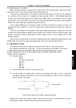
Note:
:
In fixed cycle program,
№
078
~
№
082 means the current section’s start position, but not the program
segment’s start position, when power off.
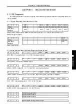
5.2 PLC State
This part of diagnosis is used to detect the signal state of machine
→
PLC
(
X
)
, PLC
→
machine
(
Y
)
,CNC
→
PLC
(
F
)
,PLC
→
CNC
(
G
)
and alarm address A, which can’t be modified. See the relative PLC
manual for address F, G significance, and the signal significance of address A is defined by user himself.
5.2.1 X Address (Fixed Addresses)
X0000
ESP
DECX
Содержание 980MDc
Страница 19: ...GSK980MDc Milling CNC User Manual XVIII ...
Страница 20: ...1 I Programming Programming Ⅰ ...
Страница 21: ...GSK980MDc Milling CNC System User Manual 2 I Programming ...
Страница 139: ...GSK980MDc Milling CNC System User Manual 120 I Programming ...
Страница 191: ...GSK980MDc Milling CNC System User Manual 172 I Programming ...
Страница 192: ...173 Ⅱ Operation Ⅱ Operation ...
Страница 193: ...GSK980MDc Milling CNC System User Manual 174 Ⅱ Operation ...
Страница 200: ...Chapter 1 Operation Mode and Display 181 Ⅱ Operation ...
Страница 201: ...GSK980MDc Milling CNC System User Manual 182 Ⅱ Operation ...
Страница 249: ...GSK980MDc Milling CNC System User Manual 230 Ⅱ Operation ...
Страница 253: ...GSK980MDc Milling CNC System User Manual 234 Ⅱ Operation ...
Страница 259: ...GSK980MDc Milling CNC System User Manual 240 Ⅱ Operation ...
Страница 265: ...GSK980MDc Milling CNC System User Manual 246 Ⅱ Operation ...
Страница 293: ...GSK980MDc Milling CNC System User Manual 274 Ⅱ Operation ...
Страница 295: ...GSK980MDc Milling CNC System User Manual 276 Ⅱ Operation ...
Страница 319: ...GSK980MDc Milling CNC System User Manual 300 Ⅱ Operation ...
Страница 320: ...301 Ⅲ Installation Ⅲ Installation ...
Страница 321: ...GSK980MDc Milling CNC System User Manual 302 Ⅲ Installation ...
Страница 345: ...GSK980MDc Milling CNC System User Manual 326 Ⅲ Installation ...
Страница 391: ...GSK980MDc Milling CNC System User Manual 372 Ⅲ Installation ...
Страница 392: ...Appendix 373 Appendix Appendix ...
Страница 393: ...GSK980MDc Milling CNC System User Manual 374 Appendix ...
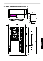
Страница 394: ...Appendix 375 Appendix Appendix 1 Outline Dimension of GSK980MDc L N ...


