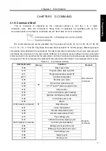
Chapter 3 G Command
33
I Programming
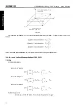
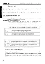
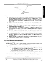
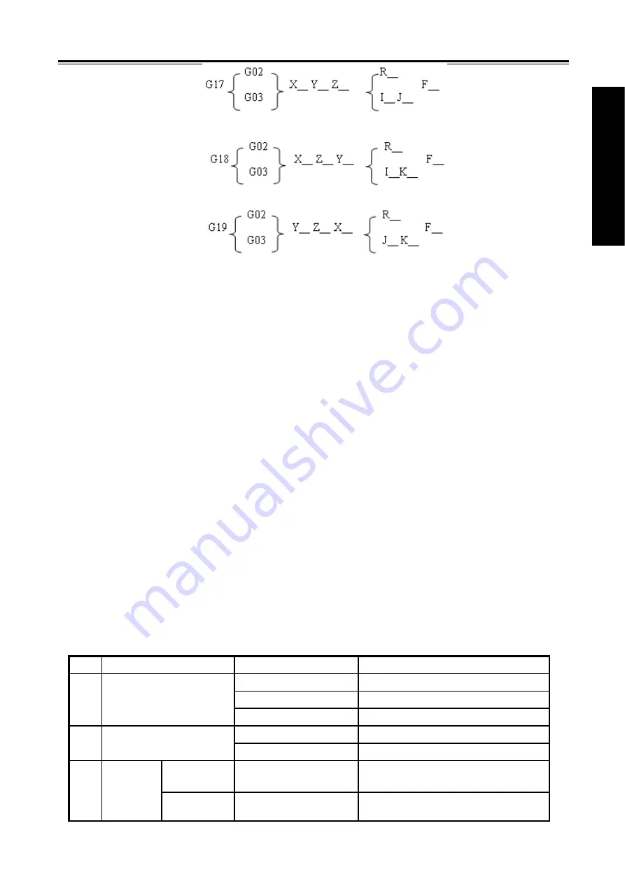
Arc interpolation in XZ plane, Y axis linear interpolation linkage;
Arc interpolation in YZ plane, X axis linear interpolation linkage;
Function:
Only two axes of circular interpolation can be linked for controlling tool movement along with the
arc on the selected plane in any time. If the 3rd axis is specified simultaneously in linear
interpolation mode, it will be linked by linear interpolation type to constitute helical interpolation.
G02 movement path is CW from start to end points. G03 movement path is CCW from start to
end points.
Explanation:
G02 and G03 are modal G commands;
R is an arc radius, its value
:
-99999999
~
99999999×least input increment
;
When the circle center is specified by address I, J and K, they are corresponding with the X, Y and Z
axes separately.
I is the difference between the center point and the arc start point in the X axis direction, I= center
point coordinate X- X coordinate of arc start point; its value
:
-99999999
~
99999999×least input
increment;
J is the difference between the center point and the arc start point in the Y axis direction, J=center
point coordinate Y- Y coordinate of circle arc start point; its value
:
-99999999
~
99999999×least input increment ;
K is the difference between the center point and circle start point in the Z axis direction, K=center
point coordinate Z- Z coordinate of circle start point; its value
:
-99999999
~
99999999×least input
increment.
Note
:
When I, J and K are for whole-circle that they have signs according to the direction. And they are positive
values when I, J and K share the same directions with X, Y and Z axes; otherwise they are negative ones.
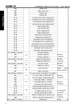
Item
Specified content
Command
Meaning
G17
Specifying XY plane arc
G18
Specifying ZX plane arc
1 Plane
specification
G19
Specifying YZ plane arc
G02 CW
2 Rotating
direction
G03 CCW
G90 mode Two axes of X, Y and Z
End point in the part
coordinate system
3 End
point
G91 mode Two axes of X, Y and Z
Distance from start to end points
Содержание 980MDc
Страница 19: ...GSK980MDc Milling CNC User Manual XVIII ...
Страница 20: ...1 I Programming Programming Ⅰ ...
Страница 21: ...GSK980MDc Milling CNC System User Manual 2 I Programming ...
Страница 139: ...GSK980MDc Milling CNC System User Manual 120 I Programming ...
Страница 191: ...GSK980MDc Milling CNC System User Manual 172 I Programming ...
Страница 192: ...173 Ⅱ Operation Ⅱ Operation ...
Страница 193: ...GSK980MDc Milling CNC System User Manual 174 Ⅱ Operation ...
Страница 200: ...Chapter 1 Operation Mode and Display 181 Ⅱ Operation ...
Страница 201: ...GSK980MDc Milling CNC System User Manual 182 Ⅱ Operation ...
Страница 249: ...GSK980MDc Milling CNC System User Manual 230 Ⅱ Operation ...
Страница 253: ...GSK980MDc Milling CNC System User Manual 234 Ⅱ Operation ...
Страница 259: ...GSK980MDc Milling CNC System User Manual 240 Ⅱ Operation ...
Страница 265: ...GSK980MDc Milling CNC System User Manual 246 Ⅱ Operation ...
Страница 293: ...GSK980MDc Milling CNC System User Manual 274 Ⅱ Operation ...
Страница 295: ...GSK980MDc Milling CNC System User Manual 276 Ⅱ Operation ...
Страница 319: ...GSK980MDc Milling CNC System User Manual 300 Ⅱ Operation ...
Страница 320: ...301 Ⅲ Installation Ⅲ Installation ...
Страница 321: ...GSK980MDc Milling CNC System User Manual 302 Ⅲ Installation ...
Страница 345: ...GSK980MDc Milling CNC System User Manual 326 Ⅲ Installation ...
Страница 391: ...GSK980MDc Milling CNC System User Manual 372 Ⅲ Installation ...
Страница 392: ...Appendix 373 Appendix Appendix ...
Страница 393: ...GSK980MDc Milling CNC System User Manual 374 Appendix ...
Страница 394: ...Appendix 375 Appendix Appendix 1 Outline Dimension of GSK980MDc L N ...


