Appendix
427
Appendix
DT34
Delay time after spindle auto gear shift in position
DT35
Check time of the auto gear shift
DT33: The initialization for 5 seconds, users can set the parameter to adjust it. but don’t set too short time
to cause the spindle damage due to little time for spindle switching in to lower gear stage; too long times
means
Timeliness is relatively low and
processing efficiency affected.
DT34: The initialization for 5 seconds, users can set the parameter to adjust it, but don’t set too short time
that spindle cannot reach the appointed speed during the
M instruction implement; too long to affect
the
processing efficiency
.
z
Action sequence
The action sequence is as below according to control logic:
z
Control logic
¾
When K13.7 parameter set to 1, spindle auto gear shift function is valid;
¾
To implement any of M41,M42,M43,M44, judge input gear-stage is consistent with the current one
or not, else gear stage should shift;
¾
Gear shift starts, CNC outputs analog voltage set by parameterDT30 to spindle servo or frequency
converter;
¾
After a time set by parameterDT31(gear shift time1)
后
, shut gear-stage output signal and output
new gear shift signal;
¾
Check gear shift completed or not, if not, wait for complete signal;
¾
In a time set by DT33, if gear shift is not completed then perform alarm A1.0;
If gear shift is completed, delaying for a time set by parameter DT32(gear shift time 2), then CNC
outputs analog voltage set by parameterNO101
~
NO104, according to the current gear-stage. That
gear shift process is completed.
Note 1: only the
number of spindle revolutions is in the analog voltage control, is the
spindle
auto gear shift function valid;
Note 2: if spindle function is invalid, perform M41
~
M44 alarm;
Note 3: It needs checking in position signal that spindle gear shift function takes actions.
After having checked in position signal, the gear shift function can complete.
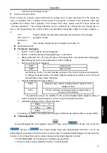
11.2.4 Spindle Switching Volume Control
z
Related signal
Содержание 980MDc
Страница 19: ...GSK980MDc Milling CNC User Manual XVIII ...
Страница 20: ...1 I Programming Programming Ⅰ ...
Страница 21: ...GSK980MDc Milling CNC System User Manual 2 I Programming ...
Страница 139: ...GSK980MDc Milling CNC System User Manual 120 I Programming ...
Страница 191: ...GSK980MDc Milling CNC System User Manual 172 I Programming ...
Страница 192: ...173 Ⅱ Operation Ⅱ Operation ...
Страница 193: ...GSK980MDc Milling CNC System User Manual 174 Ⅱ Operation ...
Страница 200: ...Chapter 1 Operation Mode and Display 181 Ⅱ Operation ...
Страница 201: ...GSK980MDc Milling CNC System User Manual 182 Ⅱ Operation ...
Страница 249: ...GSK980MDc Milling CNC System User Manual 230 Ⅱ Operation ...
Страница 253: ...GSK980MDc Milling CNC System User Manual 234 Ⅱ Operation ...
Страница 259: ...GSK980MDc Milling CNC System User Manual 240 Ⅱ Operation ...
Страница 265: ...GSK980MDc Milling CNC System User Manual 246 Ⅱ Operation ...
Страница 293: ...GSK980MDc Milling CNC System User Manual 274 Ⅱ Operation ...
Страница 295: ...GSK980MDc Milling CNC System User Manual 276 Ⅱ Operation ...
Страница 319: ...GSK980MDc Milling CNC System User Manual 300 Ⅱ Operation ...
Страница 320: ...301 Ⅲ Installation Ⅲ Installation ...
Страница 321: ...GSK980MDc Milling CNC System User Manual 302 Ⅲ Installation ...
Страница 345: ...GSK980MDc Milling CNC System User Manual 326 Ⅲ Installation ...
Страница 391: ...GSK980MDc Milling CNC System User Manual 372 Ⅲ Installation ...
Страница 392: ...Appendix 373 Appendix Appendix ...
Страница 393: ...GSK980MDc Milling CNC System User Manual 374 Appendix ...
Страница 394: ...Appendix 375 Appendix Appendix 1 Outline Dimension of GSK980MDc L N ...


