background image

01000\R06eng 

0704 

Repair Instructions 

and 

Spare Parts Lists  

for 


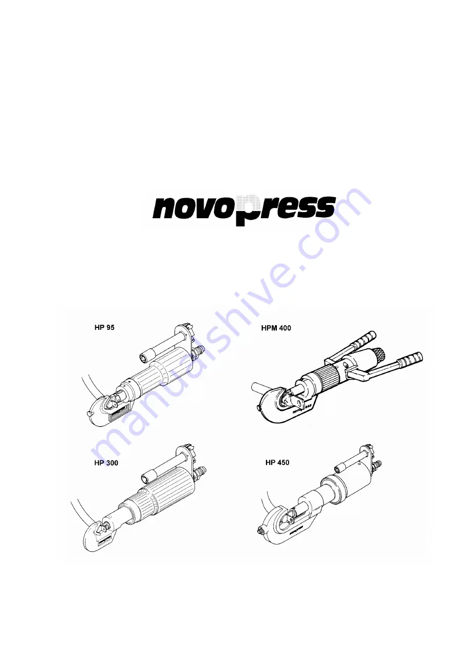
PRESSING CYLINDERS 


16566 

Содержание HP 300

Страница 1: ...01000 R06eng 0704 Repair Instructions and Spare Parts Lists for PRESSING CYLINDERS 16566 ...

Страница 2: ...ch HP 95 and HP 300 10 Pressing Cylinder HP 300 Dismantling 14 Assembly 16 Parts list and exploded view 18 Pressing Cylinder HPM 400 Dismantling 22 Assembly 24 Parts list and exploded view 27 Pressing Cylinder HP 450 Dismantling 30 Assembly 32 Parts list and exploded view 34 31831 Hand switch HP 450 38 7375 Valve 40 30645 Punch stop 41 30655 Die stop 41 ...

Страница 3: ...r gloves and non slip footwear Wear a hair net if you have long hair 4 Always be alert Only use a device after having been instructed in its operation Concentrate on your work Proceed sensibly Do not use the device when you are distracted 5 Do not lean too far forward Avoid abnormal stance Make sure that you have a secure standing position and maintain balance at all times 6 Leave safety devices w...

Страница 4: ... PRESSURE Avoid squashing or bending of the piping Piping must not be painted over 7 Replace the hydraulic piping when cracks squashed or bent points are to be seen when blistering is established when hydraulic fluid escapes when pipe fittings are damaged when discolouration is established on the outer layer e g due to the influence of solvents 8 The hydraulic fluid used in the system is kerosene ...

Страница 5: ... individual drawing of the corresponding part of the tool 23 refers to item 23 of corresponding pressing cylinder 3 31830 refers to item 3 of the parts list 31830 NOTE 3 31830 refers to item 3 of Spare Parts List 31830 Item 3 in this case lock nut Spare Parts List 31830 in this case hand switch HP 95 and HP 300 ...

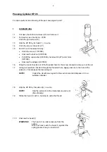
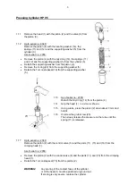
Страница 6: ...pter 4 31830 1 6 Draw the control bar 9 out of the threaded hole for the screw connector and pour out the oil 1 7 Using a screwdriver inserted through the threaded hole apply pressure to the hole of the valve 6 This releases the remaining oil NOTE Collect the oil with due regard to the environment and dispose of it in a suitable container 1 8 Grip the HP 95 by the piston 3 in a vice NOTE Grip the ...

Страница 7: ...washer 5 1 13 As of serial no 2350 Detach the Glyd ring 14 from the piston 4 1 14 Grip the head 1 in a vice as shown 1 15 Using a tube press the piston 2 down about 3 mm and hold it 1 16 Unscrew the grub screw 20 Then slowly release the pressure on the tube until the spring 11 is released 1 17 Up to serial no 2349 Remove the piston 2 with the control valve 6 and the parts 11 15 and 16 from the cri...

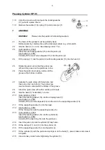
Страница 8: ...ible 2 7 Advance the grub screw 20 fully home and then retire it by one full turn The grub screw must not make contact with the bottom of the groove 2 8 Arrest the grub screw 20 with a centre punch mark 2 9 Grip the head 1 horizontally in a vice 2 10 Up to serial no 2349 Insert the locating washer 16 into the crimping head 1 As of serial no 2350 Correctly fit the Turcon stepseal 16 into the slot i...

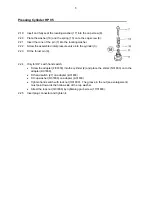
Страница 9: ...er 3 2 23 Fit the thrust pin 9 2 24 Only for HP s with hand switch Screw the adapter 4 31830 into the cylinder 2 and place the shims 5 31830 on to the adapter 4 31830 Fit hand switch 27 on adapter 4 31830 Fit cup washer 6 31830 on adapter 4 31830 Tighten hand switch with lock nut 3 31830 The groove in the nut see enlargement must point towards the hollow side of the cup washer Arrest the lock nut ...

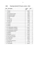
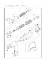
Страница 10: ...rew 1498 1 9 Thrust pin 1499 1 11 Spring 1215 2 12 Spring 1216 1 13 Spring 1613 1 14 Locating washer 50x35x10 11061 1 15 Locating washer 37x30x8 4 11059 1 16 Locating washer 38x26x8 5 11060 1 17 Locating washer 3x7x3 11056 1 18 Washer 4241 1 19 Bushing 11062 1 20 Grub screw AM 8x16 11052 1 21 Plug connector R3 8 3718 1 23 Shrink sleeve 16728 1 24 Tool label 5693 1 25 Dust cap for plug end 1514 1 2...

Страница 11: ...7 3000 Pressing Cylinder HP 95 up to serial no 2349 ...

Страница 12: ... screw M 4x6 11758 1 11 Spring 1215 2 12 Spring 1216 1 13 Spring 1613 1 14 Glyd ring ø50xø39 3x4 2 16247 1 15 Turcon Stepseal ø37xø29 7x3 2 16248 1 16 Turcon Stepseal ø26xø36 7x4 2 16249 1 17 Locating washer 3x7x3 11056 1 18 Washer 4241 1 19 Bushing 11062 1 20 Grub screw AM 8x16 11052 1 21 Plug connector R3 8 3718 1 22 O ring 40 2x3 16246 1 23 Shrink sleeve 16728 1 24 Tool label 5693 1 25 Dust cap...

Страница 13: ...9 3000 Pressing Cylinder HP 95 as of serial no 2350 ...

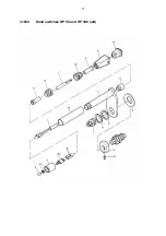
Страница 14: ...5 2 6 Cup washer 14231 1 7 Cable 14235 1 8 Extension 14242 1 9 Protective sleeve 14271 2 10 Cable grip 14270 2 11 Sleeve casing 14219 1 12 Insert plug 14218 1 13 Push switch 14186 1 14 Push button 14187 1 15 Shrink sleeve 14237 2 16 Shrink sleeve 14245 1 17 Grub screw M5x10 11078 1 Note The new hand switch see page 12 must be fitted if handle 31823 is defective ...

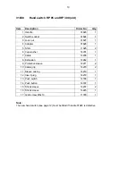
Страница 15: ...11 31830 Hand switches HP 95 and HP 300 old ...

Страница 16: ...12 31830 Hand switch HP 95 and HP 300 new Item Description Order No Qty 1 Handle 36960 1 3 Lock nut 31827 1 4 Adapter 31826 1 5 Shim 11025 2 6 Cup washer 14231 1 17 Grub screw M5x10 11078 1 ...

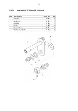
Страница 17: ...o Qty 1 Handle 31823 1 2 Switch socket 31824 1 3 Wire 14834 2 4 Pan head screw M3 x 8 13127 2 5 Serrated lock washer A3 2 14215 2 6 Housing 14243 1 7 Insert plug 14218 1 8 Push switch 14186 1 9 Push button 14187 1 10 Shrink sleeve 14237 2 11 Shrink sleeve 14245 1 ...

Страница 18: ...31830 hand switch 36 and shims 5 31830 Unscrew and remove the adapter 4 31830 3 6 Take the thrust pin 28 out of the tapped hole for the plug connector and tip out the oil 3 7 Press against the cone of the valve 30 with a screw driver inserted through the tapped hole The remaining oil will run out NOTE Collect the oil with due regard to the environment and dispose of it in a suitable container 3 8 ...

Страница 19: ... wire 3 14 Remove washer 31 spring 25 and conical pin 26 3 15 Grip the HP 300 in a vice as illustrated 3 16 Unscrew the cylinder 2 from the cylinder 3 To unscrew the cylinder use a monkey wrench for a diameter of D 68 75mm WARNING The cylinder is under pressure Push the cylinder against the spring pressure with one hand to unscrew it 3 17 Up to serial no 3400 Take the spiral spring 19 the piston 4...

Страница 20: ...lyd ring 16 onto the piston 4 4 3 Fit the piston 4 into the cylinder 2 and push it down to the base of the cylinder As of serial no 3401 WARNING The Turcon stepseal must not be damaged by the cylinder thread 4 4 Up to serial no 3400 Insert the locating washer 15 into the cylinder 3 and push down to the base of the cylinder As of serial no 3401 Insert Turcon stepseal 15 into the slot in the cylinde...

Страница 21: ...mbled inlet pressure valve into the cylinder 2 4 18 Insert the thrust pin 28 4 19 For HP s with hand switch only Screw the adapter 4 31830 into the cylinder 2 and push the shims 5 31830 on to the adapter 4 31830 Push the hand switch 36 on to the adapter 4 31830 Push the cup washer 6 on to the adapter 4 31830 Tighten the hand switch with the lock nut 3 31830 The groove in the nut see enlargement mu...

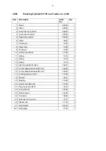
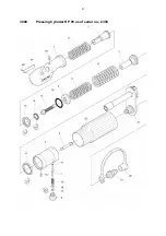
Страница 22: ... 65x50x10 11055 1 17 Locating washer 3x7x3 11056 1 18 Spring 4593 1 19 Spring 4 5x46x135 2487 1 20 Plug connector R3 8 Tool plug 3718 1 21 Shrink sleeve 16669 1 25 Spring 1612 1 26 Conical pin 1497 1 27 Bushing A 2 5x9 11058 1 28 Thrust pin 1500 1 29 Cap screw 1498 1 30 Valve 3408 1 31 Washer 4241 1 32 Tool label 4846 1 33 Ribbed nail 2x6 11120 2 34 Grub screw M5 x 8 45H 11669 1 35 Dust cap for pl...

Страница 23: ...19 1000 Pressing Cylinder HP 300 up to serial no 3400 ...

Страница 24: ...urcon Stepseal ø32xø42 7x4 2 16238 1 16 Glyd ring ø65xø54x4 2 16242 1 17 Locating washer 3x7x3 11056 1 18 Spring 4593 1 19 Spring 4 5x46x135 2487 1 20 Plug connector R3 8 Tool plug 3718 1 21 Shrink sleeve 16669 1 25 Spring 1612 1 26 Conical pin 1497 1 27 Bushing A 2 5x9 11058 1 28 Thrust pin 1500 1 29 Cap screw 1498 1 30 Valve 3408 1 31 Washer 4241 1 32 Tool label 4846 1 32 20 Tool label Abiko 122...

Страница 25: ...21 1000 Pressing Cylinder HP 300 as of serial no 3401 ...

Страница 26: ...e of it in a suitable container 5 5 Remove the two plugs 76 5 6 Undo the two grub screws 69 5 7 Withdraw the two bolts 14 Use an M 3x50 mm screw 5 8 Remove the levers 4 5 9 Take off the protective cover 16 5 10 Undo the two screws 70 5 11 Take off the suction cup 15 with the pump housing 3 Do not lose the O ring 52 Take off the rings 9 and 13 and remove the suction cup from the pump housing 5 12 T...

Страница 27: ...essure 5 19 Undo the screw 37 5 20 Release the pressure on the piston slowly until the spring 41 is released Remove the piston 5 21 Undo the cap screw 23 and remove it from the piston With the special spanner Order No 8134 5 22 Remove the spring 26 and washer 22 5 23 Replace seals 46 51 and 56 5 24 Remove the thrust pin 80 from the cylinder 2 Box spanner 27mm 5 25 Push the piston 6 out of the cyli...

Страница 28: ...t engage the piston groove 6 7 Fit the piston 6 into the cylinder 2 6 8 Using a screwdriver place the cup springs 66 on to the piston 6 6 9 Fit the thrust pin 80 into the cylinder 2 6 10 Place the spring 27 on the valve sleeve 6 11 Assemble the cylinder and head WARNING Screw the piston fully home into the head The hole in the cylinder must be visible through the tapped hole for the screw 43 If th...

Страница 29: ...r 6 23 Dust the protective cover 16 from the inside with talcum powder and then fit it on to the HPM 400 The hole in the protective cover should be positioned over the screw 68 6 24 Using an implement open lift the pressure relief valve until the piston is retracted 6 25 Fit the pump lever Insert the bolt 14 and tighten the grub screws 69 6 26 Insert the plug 76 into the protective cover 6 27 Remo...

Страница 30: ...26 ...

Страница 31: ... Bolt 5449 2 15 Suction cup 5581 1 16 Protective cover 5582 1 17 Piston 5621 1 21 Valve piston 5476 1 22 Washer 5477 1 23 Cap screw 5474 1 24 Set screw 5473 1 25 Valve washer 6628 1 26 Spring 5806 1 28 Valve washer 5635 1 29 Conical pin 5642 1 30 Cap screw 5643 1 31 Rotary knob 5644 1 32 Shim 5646 2 33 Shim 5647 3 34 Ring 5645 1 35 Valve screw 6629 1 36 Protective sleeve 5709 1 37 Screw 4541 1 38 ...

Страница 32: ...O ring 11714 1 56 O ring 11955 1 57 Usit ring 11369 1 59 Ball Ø 5 11340 1 60 Ball Ø 5 11116 3 62 Spring 11957 2 63 Spring 6631 1 64 Spring 11960 1 65 Circlip 11961 1 66 Cup spring 11962 2 68 Grub screw 11963 2 69 Grub screw 11964 2 70 Hex head bolt 11965 2 71 Tool label 5649 1 72 Ribbed nail 11120 2 73 Circlip 11968 1 74 Filter disk 11969 1 75 Split taper pin 11146 1 76 Plug 5813 3 77 Case for HP ...

Страница 33: ...29 5200 Pressing Cylinder HPM 400 ...

Страница 34: ...n 10 for the plug connector through the threaded hole and tip out the oil 7 6 Press against the ball of the valve 43 with a screwdriver inserted through the threaded hole The remaining oil will run out NOTE Collect the oil with due regard to the environment and dispose of it in a suitable container 7 7 Grip the HP 450 in a vice as illustrated NOTE Grip the cylinder at the inlet pressure valve See ...

Страница 35: ... washer 8 7 18 Using a tube press and hold the piston 2 down by hand overcoming the spring pressure 7 19 Undo the screw M 10 x 30 and remove it together with the washer Ø 10 5 7 20 Slowly reduce the pressure until the spring 16 is fully released 7 21 Remove the piston 2 with valve 43 and seal 26 from the head 1 7 22 Unscrew the cap screw 15 and the locating washer 27 and push out with a length of ...

Страница 36: ...th the retaining ring 3 30655 8 13 Insert the piston 6 with the new O ring 24 into the cylinder 5 8 14 Insert the spring 18 into the cylinder 5 8 15 Offer the cylinder 5 with its fittings up to the head 1 press it against the spring pressure and screw on to the head 8 16 Tighten the cylinder 5 with a monkey wrench 8 17 Fit the locating washer 27 into the cap screw 15 and press it fully home 8 18 P...

Страница 37: ...33 ...

Страница 38: ...pring SH 3851 1 18 Spring low pressure 3852 1 20 Spring 1612 1 23 Spring 11808 1 24 O ring 11689 1 25 Locating washer 35 x 50 x 10 12089 1 26 Locating washer 50 x 42 x 8 11691 1 27 Locating washer 3 x 7 x 3 11056 1 28 Bushing 11058 1 31 Washer 4241 1 32 Guide pin 3940 1 33 Ball 11340 1 34 Retaining washer 11813 1 36 Plug connector 3718 1 37 Retaining ring 11815 1 38 Shrink sleeve 12008 1 39 Split ...

Страница 39: ...35 3850 Pressing Cylinder HP 450 ...

Страница 40: ... Cup spring 14231 1 7 Cable 14236 1 8 Extension 14242 1 9 Protective sleeve 14271 2 10 Cable grip 14270 2 11 Sleeve casing 14219 1 12 Insert plug 14218 1 13 Push switch 14186 1 14 Pushbutton 14187 1 15 Shrink sleeve 14237 2 16 Shrink sleeve 14244 1 17 Grub screw M5x10 11078 1 Note The new hand switch see page 38 must be fitted if handle 31821 is defective ...

Страница 41: ...37 31831 Hand Switch HP 450 old ...

Страница 42: ...38 31831 Hand Switch HP 450 new Item Description Order No Qty 1 Handle 36961 1 3 Lock nut 31827 1 4 Adapter 31826 1 5 Shim 11025 2 6 Cup spring 14231 1 17 Grub screw M5x10 11078 1 ...

Страница 43: ...y 1 Handle 31821 1 2 Switch socket 31824 1 3 Wire 14834 2 4 Pan head screw M3 x 8 13127 2 5 Serrated lock washer A3 2 14215 2 6 Housing 14243 1 7 Insert plug 14218 1 8 Push switch 14186 1 9 Pushbutton 14187 1 10 Shrink sleeve 14237 2 11 Shrink sleeve 14244 1 ...

Страница 44: ...40 7375 Valve HP 450 complete Item Description Order No Qty 9 Spring sleeve 3936 1 13 Ball 1541 1 19 Spring 1218 1 29 Socket head bolt M 5x90 11068 1 30 Hex nut M5 11065 1 ...

Страница 45: ...645 Punch Stop Item Description Order No Qty 1 Lock pin 30646 1 2 Knurled nut 30647 1 3 Spring 13812 1 30655 Die stop Item Description Order No Qty 1 Lock pin 3939 1 2 Spring 3854 1 3 Retaining ring 11814 1 ...

Страница 46: ...Repair Service Scharnhorststraße 1 P O Box 101163 D 41460 Neuss 1 D 41411 Neuss Tel 02131 288 0 Fax 02131 28855 ...

Отзывы: