4 - 1 3
4
Communication Interfaces
DISPLAY
REPO
NC NO
EXT. BATT
TEMP.
BT1 BT2
EXT.SWITCH
STATUS
S1
S2
S3
S4
BT3 BT4
O/P DRY
CONTACT
USB
RS-232
P1
P2
P3
P4
P5
P6
I/P DRY
CONTACT
P1
P2
BATT.
START
BATT.
START
P3
P4
PARALLEL
USB Port & RS-232 Port
(Figure 4-16: Location of USB Port & RS-232 Port)
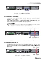
4.1.11 Auxiliary Power Cards
The UPS has two auxiliary power cards. Each card has one LED indicator. Please see
Figure 4-17
for their location.
If the auxiliary power card works normally, its LED indicator will illuminate green. If the
DX[LOLDU\SRZHUFDUGLVRႇRUDEQRUPDOLWV/('LQGLFDWRUZLOOEHRႇ
WARNING:
The UPS has two hot-swappable auxiliary power cards. For replacement, you can
only replace one card at one time to avoid power interruption.
DISPLAY
REPO
NC NO
EXT. BATT
TEMP.
BT1 BT2
EXT.SWITCH
STATUS
S1
S2
S3
S4
BT3 BT4
O/P DRY
CONTACT
USB
RS-232
P1
P2
P3
P4
P5
P6
I/P DRY
CONTACT
P1
P2
BATT.
START
BATT.
START
P3
P4
PARALLEL
Auxiliary Power Card’s
LED Indicator
Auxiliary Power Card’s
LED Indicator
Auxiliary
Power Card
Auxiliary
Power Card
(Figure 4-17: Location of Auxiliary Power Cards and Their LED Indicators)
4.1.12 Battery Start Buttons
Please refer to
Figure 4-18
for the location of battery start buttons. For the battery start
buttons’ relevant operation information, please refer to
6.2.2 Battery Mode Start-up
Procedures
.
DISPLAY
REPO
NC NO
EXT. BATT
TEMP.
BT1 BT2
EXT.SWITCH
STATUS
S1
S2
S3
S4
BT3 BT4
O/P DRY
CONTACT
USB
RS-232
P1
P2
P3
P4
P5
P6
I/P DRY
CONTACT
P1
P2
BATT.
START
BATT.
START
P3
P4
PARALLEL
Battery Start Button
Battery Start Button
(Figure 4-18: Location of Battery Start Buttons)
Содержание Modulon DPH series
Страница 26: ......
Страница 58: ......
Страница 168: ......
Страница 237: ...8 1 8 Optional Accessories 8 Optional Accessories...
Страница 240: ......
Страница 241: ...9 1 9 Maintenance Maintenance 9...
Страница 243: ...A1 1 Appendix 1 7HFKQLFDO 6SHFL FDWLRQV Technical 6SHFL FDWLRQV A1 A1...
Страница 246: ......
Страница 247: ...A2 1 Appendix 2 Warranty Warranty A2 A2...
Страница 250: ......


