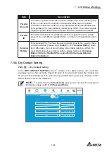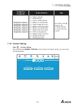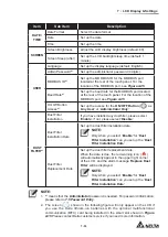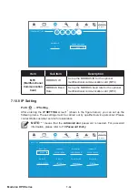
7 - 5 9
7
LCD Display & Settings
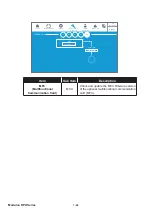
NOTE:
1.
*
1
means that the
Administrator
password is needed. For password
information, please refer to
7.5 Password Entry
.
2.
*
2
means that the
Alarm Threshold Values (High & Low)*
2
are defined by
the service personnel during the installation process of the optional battery
management system (BMS).
3.
*
3
means that the item will only show up after you select ‘
Main
’ in the
Module
list.
On-Line
UPS-1.1
LOG IN
Administrator
BMS SETTING
10:15
Sep 25,2018
MEASUREMENT
4
WARNING
MAINTENANCE
Main
BMS Setting
SETUP
1
1
Internal Resistance
Enable
Module
Module Address
String ID
Module Type
Status
Cell Voltage (V)
String Voltage (V)
Ambient Temperature (°C)
Alarm Threshold Setting Values
High
15.0
576.0
70.0
Low
10.5
368.0
25.0
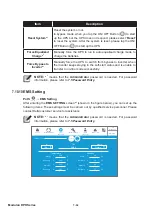
Item
Description
Module
Set the module as Main/ Ext #n.
Module Address
Set the module address.
Module Type
Set the module type as Voltage Type/ internal Resistance.
Status
The status ‘
Enable
/
Disable
’ determines whether or not the LCD
shows the BMS information of the optional battery management
system (BMS).
Содержание Modulon DPH series
Страница 26: ......
Страница 58: ......
Страница 168: ......
Страница 237: ...8 1 8 Optional Accessories 8 Optional Accessories...
Страница 240: ......
Страница 241: ...9 1 9 Maintenance Maintenance 9...
Страница 243: ...A1 1 Appendix 1 7HFKQLFDO 6SHFL FDWLRQV Technical 6SHFL FDWLRQV A1 A1...
Страница 246: ......
Страница 247: ...A2 1 Appendix 2 Warranty Warranty A2 A2...
Страница 250: ......


