5 - 3 5
5
Installation and Wiring
The STS module’s LED indicator shows its operation status. Please refer to the following
table.
LED Indicator
Description
OFF
The STS module is OFF.
ON (yellow)
The STS module is working in bypass mode,
ECO mode, or energy recycle mode.
Flashing (yellow)_ on for 0.3
VHFRQGDQGRႇIRUVHFRQGV
The STS module is abnormal.
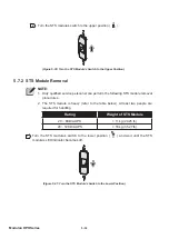
NOTE:
In bypass mode, if you turn the STS module’s switch to the lower position (
), the
676PRGXOHZLOOVKXWGRZQDQGLWVRXWSXWDQGLWV/('LQGLFDWRUZLOOEHRႇ
5.8 Power Module (Optional)
NOTE:
1. The UPS has two different system cabinets, 20 ~ 80kVA and 20 ~ 120 kVA.
Their exterior and size are the same (see
Figure 2-1
and
Figure 2-2
), but
their power module slot’s quantity, location, STS module’s size and weight are
GLႇHUHQWVHH
2.6 Internal View
and
Figure 2-4
).
2. For these two system cabinets, their power modules and STS modules’
installation and removal methods are the same; thus, the diagram of 20 ~ 120
kVA cabinet is mostly taken as an example in chapters
5.8 Power Module
(Optional)
,
5.8.1 Power Module Installation
, and
5.8.2 Power Module
Removal
.
The power module is optional (not included in the package of the UPS). It is hot swappable
and each capacity is 20kVA/ 20kW. Please follow your UPS capacity to install the correct
number of power modules. Please refer to the table below.
UPS Capacity
20kVA/
20kW
40kVA/
40kW
60kVA/
60kW
80kVA/
80kW
100kVA/
100kW
120kVA/
120kW
Power Module Q’ty
1
2
3
4
5
6
Содержание Modulon DPH series
Страница 26: ......
Страница 58: ......
Страница 168: ......
Страница 237: ...8 1 8 Optional Accessories 8 Optional Accessories...
Страница 240: ......
Страница 241: ...9 1 9 Maintenance Maintenance 9...
Страница 243: ...A1 1 Appendix 1 7HFKQLFDO 6SHFL FDWLRQV Technical 6SHFL FDWLRQV A1 A1...
Страница 246: ......
Страница 247: ...A2 1 Appendix 2 Warranty Warranty A2 A2...
Страница 250: ......


