7 - 4
Modulon DPH Series
NOTE:
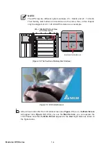
7KH836KDVWZRGLႇHUHQWV\VWHPFDELQHWVaN9$DQGaN9$
Their battery start buttons and locations are the same; thus, in this chapter,
only the diagram of 20 ~ 120 kVA UPS is taken as an example.
DISPLAY
REPO
NC
NO
EXT. BATT
TEMP.
BT1 BT2
EXT.SWITCH
STATUS
S1
S2
S3
S4
BT3 BT4
O/P DRY
CONTACT
USB
RS-232
P1
P2
P3
P4
P5
P6
I/P DRY
CONTACT
P1
P2
BATT.
START
BATT.
START
P3
P4
PARALLEL
DISPLA
Y
EMS
/CONSOLE
RESET
GND B A GND B A
MODBUS BMS
BATT.
START
BATT.
START
(20 ~ 120kVA UPS Front View
with Door Open)
Battery Start Button x 2
(Figure 7-2: The Position of Battery Start Buttons)
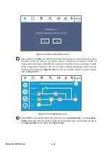
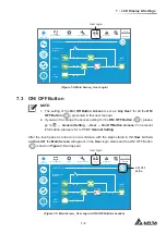
(Figure 7-3: LCD Initial Screen)
2
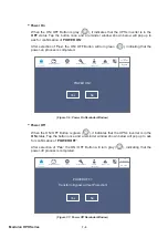
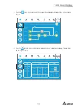
About 20 seconds after the LCD initial screen (see
Figure 7-3
) is on, the
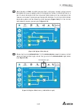
Main Screen
will appear (see
Figure 7-4
). After you see the
Main Screen
, you can operate the
LCD. Please note that the
Main Screen
appears in the
User
login status as shown in
WKH¿JXUHEHORZ
Содержание Modulon DPH series
Страница 26: ......
Страница 58: ......
Страница 168: ......
Страница 237: ...8 1 8 Optional Accessories 8 Optional Accessories...
Страница 240: ......
Страница 241: ...9 1 9 Maintenance Maintenance 9...
Страница 243: ...A1 1 Appendix 1 7HFKQLFDO 6SHFL FDWLRQV Technical 6SHFL FDWLRQV A1 A1...
Страница 246: ......
Страница 247: ...A2 1 Appendix 2 Warranty Warranty A2 A2...
Страница 250: ......


