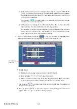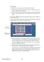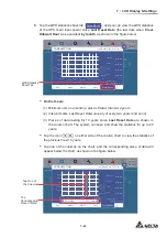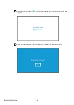
7 - 4 0
Modulon DPH Series
7.9.7.1 Connecting the optional EMS 1000 (EnviroProbe)
1. You can connect a maximum of 16 optional EMS 1000 (EnviroProbe) devices to each
UPS to expand the environment monitoring range. A maximum of 8 UPS units can
be paralleled. Please use the CAT-5 cable (user-supplied & the cable length depends
on the on-site application and environment) to connect the EMS 1000 (EnviroProbe)
to the EMS port on the UPS. For the location of the EMS port, please refer to
4.2
Communication Interfaces at the Rear of the Touch Panel
; for more information
about installation of the optional EMS 1000 (EnviroProbe), please refer to
EnviroProbe
1000 Quick Guide
.
2. The UPS only supports RS485 communication mode. When installing the EMS 1000
(EnviroProbe), please set the device’s communication mode as RS485 following
3-1
Comm DIP Switch Settings
of the
EnviroProbe 1000 Quick Guide
.
<RXKDYHWRDVVLJQDGLႇHUHQW,'IRUHDFK(06(QYLUR3UREHGHYLFHFRQQHFWHG
to the UPS for the UPS to identify different devices. When installing the EMS 1000
(EnviroProbe), please set the ID # by the four ID DIP switches on the left of the device
following
3-2 ID DIP Switch Settings
of the
EnviroProbe 1000 Quick Guide
.
NOTE:
1. You must set the ID # on the LCD according to the ID DIP switch setting on
the EMS 1000 (EnviroProbe) device. Please refer to
7.10.10 EMS Setting
.
2. The ID # of each EMS 1000 (EnviroProbe) device connected to the UPS
PXVWEHGLႇHUHQW
3. When connecting more than one EMS 1000 (EnviroProbe) devices to the
UPS, you don’t have to set the ID # in numerical order.
4. To enable the EMS function of the UPS, you have to set up relevant items on the LCD
after connecting the optional EMS 1000 (EnviroProbe) to the UPS. Please refer to
7.10.10 EMS Setting
.
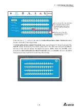
7.9.8 BMS
Path:
MEASUREMENT
ĺ%06
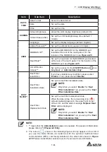
After entering the
BMS
screen (shown in the figure below), you can view the relevant
readings of
String Voltage
,
String Current
,
Ambient Temperature*
1
,
Cell Volt.
(Voltage)
and
Cell IR.*
2
(Internal Resistance) of the
Main Module
and each
Ext #n Module
of the
optional battery management system (BMS).
NOTE:
1.
*
1
means that the item will only show up after you select ‘
Main
’ in the select-
module list in the upper left corner of the screen.
2.
*
2
means that the item will only show up after you go to
SETUP
ĺ
BMS Setting
and select ‘
Internal Resistance
’ in the
Module Type
list.
Содержание Modulon DPH series
Страница 26: ......
Страница 58: ......
Страница 168: ......
Страница 237: ...8 1 8 Optional Accessories 8 Optional Accessories...
Страница 240: ......
Страница 241: ...9 1 9 Maintenance Maintenance 9...
Страница 243: ...A1 1 Appendix 1 7HFKQLFDO 6SHFL FDWLRQV Technical 6SHFL FDWLRQV A1 A1...
Страница 246: ......
Страница 247: ...A2 1 Appendix 2 Warranty Warranty A2 A2...
Страница 250: ......

