5 - 9
5
Installation and Wiring
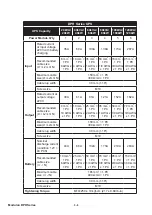
DPH Series UPS
UPS Capacity
20kVA/
20kW
40kVA/
40kW
60kVA/
60kW
80kVA/
80kW
100kVA/
100kW
120kVA/
120kW
Input Breaker (Q1)
40A
75A
125A
160A
200A
225A
Bypass Breaker (Q2)
40A
75A
125A
160A
200A
225A
Manual Bypass Breaker
(Q3)
40A
75A
125A
160A
200A
225A
Output Breaker (Q4)
40A
75A
125A
160A
200A
225A
External Battery Cabinet’s
Breaker (Q5)
50A
100A
150A
200A
250A
300A
NOTE:
1. In accordance with National Electrical Codes (NEC), please install a suitable
conduit and bushing for cable protection.
2. Please refer to national and local electrical codes for acceptable non-fuse
breakers and cable size.
3. The cables mentioned in
Table 5-2
with PVC material and with temperature
resistance up to 105°C are suggested.
4. The tightening torque for M10 screw should be 250 ± 10 kgf-cm (217 ± 8.68 lb-in).
y
To avoid UPS failure, the input of the UPS must be Y connection.
y
,IWKHUHLVDÀRDWLQJYROWDJHEHWZHHQWKHLQSXWSRZHU¶VQHXWUDO1DQGWKHJURXQG
), and
you require that the VNG of the UPS should be zero, we suggest that you install an isola-
tion transformer in front of the input side of the UPS, and connect the isolation transformer’s
secondary neutral (N) and the ground (
) to the nearest place of the transformer.
y
7KHPDLQ$&VRXUFHPXVWEHDWKUHHSKDVHIRXUZLUHV\VWHPDQGPHHWVWKHVSHFL¿FD
-
WLRQVVSHFL¿HGRQWKH836UDWLQJODEHO)RUPDLQ$&VRXUFHFRQQHFWLRQPDNHVXUHLWLV
in positive phase sequence. Please refer to
5.5.3 Single Unit Wiring
and
5.5.4 Parallel
Units Wiring
for wiring information.
y
Check the battery polarity when connecting the external battery cabinet(s) to the UPS.
Do not connect the battery polarity in reverse. For battery connection relevant informa-
tion, please refer to
5.6 External Battery Cabinet Connection Warnings
.
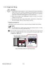
y
Connect the external battery cabinet’s grounding terminal (
) to the UPS’s grounding
terminal (
). Please refer to
Figure 5-16
and
Figure 5-18
for grounding information.
y
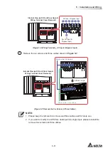
The UPS’s grounding terminal (
) must be grounded. Please use ring-type terminals when
wiring. For the location of the UPS’s grounding terminals (
), please refer to
Figure 5-11
.
Содержание Modulon DPH series
Страница 26: ......
Страница 58: ......
Страница 168: ......
Страница 237: ...8 1 8 Optional Accessories 8 Optional Accessories...
Страница 240: ......
Страница 241: ...9 1 9 Maintenance Maintenance 9...
Страница 243: ...A1 1 Appendix 1 7HFKQLFDO 6SHFL FDWLRQV Technical 6SHFL FDWLRQV A1 A1...
Страница 246: ......
Страница 247: ...A2 1 Appendix 2 Warranty Warranty A2 A2...
Страница 250: ......

