4 - 1 7
4
Communication Interfaces
4.2 Communication Interfaces at the Rear of the Touch Panel
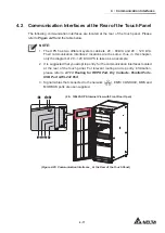
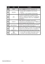
The following communication interfaces are located at the rear of the touch panel. Please
refer to
Figure 4-25
and the table below.
NOTE:
1. The UPS has two different system cabinets, 20 ~ 80kVA and 20 ~ 120 kVA.
Their communication interfaces’ locations are the same; thus, in this chapter,
only the diagram of 20 ~ 120 kVA UPS is taken as an example.
2. It is suggested that you adopt top entry for the communication interfaces located
at the rear of the touch panel. For relevant routing and top entry information,
please refer to
4.1.13 Routing for REPO Port, Dry Contacts, Parallel Ports,
USB Port & RS-232 Port
.
3. Signal cables that connected to the network (
), EMS/ CONSOLE, BMS and
MODBUS ports are user-supplied.
(20 ~ 120kVA UPS Internal View with Front Door Open)
DISPLA
Y
/CONSOLE
EMS
RESET
GND B
A GND B
A
MODBUS BMS
1
2
3
5
4
6
7
INPUT
BREAKER
OUTPUT
BREAKER
BYPASS
BREAKER
MANUAL
BYPASS
BREAKER
(Figure 4-25: Communication Interfaces _ at the Rear of the Touch Panel)
Содержание Modulon DPH series
Страница 26: ......
Страница 58: ......
Страница 168: ......
Страница 237: ...8 1 8 Optional Accessories 8 Optional Accessories...
Страница 240: ......
Страница 241: ...9 1 9 Maintenance Maintenance 9...
Страница 243: ...A1 1 Appendix 1 7HFKQLFDO 6SHFL FDWLRQV Technical 6SHFL FDWLRQV A1 A1...
Страница 246: ......
Страница 247: ...A2 1 Appendix 2 Warranty Warranty A2 A2...
Страница 250: ......


