5 - 2 0
Modulon DPH Series
4
Follow
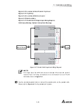
Figure 5-18
to ground the parallel UPS units, external battery cabinet(s)
and connected critical loads.
Load
Load
(At Maximum Eight)
(At Maximum Eight)
External
Battery
Cabinet
External
Battery
Cabinet
External
Battery
Cabinet
External
Battery
Cabinet
UPS
UPS
UPS Grounding
Load Grounding
Load Grounding
External Battery
Cabinet Grounding
Protective Earthing
(Figure 5-18: Grounding Diagram_ Parallel Units)
WARNING:
%HIRUHVWDUWXSRIWKHSDUDOOHOXQLWVTXDOL¿HGVHUYLFHSHUVRQQHOPXVWVHW
each UPS’s '
Parallel Group ID
' (1 or 2) and '
Parallel ID
' (1~8) through the
LCD. Otherwise, the parallel UPSs cannot be started. Please refer to
7.10.5
Parallel Setting
.
y
Dual Input (Parallel Units)
When there are two AC power sources, parallel units wiring procedures are as follows.
1
Follow
6LQJOH,QSXW'XDO,QSXW0RGL¿FDWLRQ
to modify the UPS from single
input to dual input.
2
Refer to the procedures
1
~
7
stated in the section of
Single Input (Single
Unit)
.
3
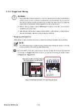
Connect the cables of the main AC source, bypass source, output and external
battery cabinet(s) to the UPS. There are two types of wiring, top wiring and bottom
wiring. Please refer to the following to perform wiring.
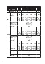
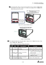
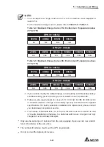
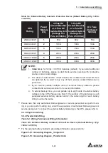
Table 5-3: Wiring Terminals & Wiring Information
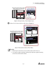
Figure 5-8: Wiring Terminals_ AC Input & Bypass Input
Figure 5-9: Wiring Terminals_ Battery Input
Figure 5-10: Wiring Terminals_ UPS Output
Figure 5-11: Wiring Terminals_ Grounding
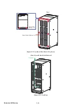
Figure 5-12: Location of Rear Panel & Top Cover
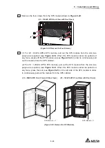
Figure 5-13: Top Entry
Figure 5-14: Location of Bottom Covers
Figure 5-15: Bottom Entry
Содержание Modulon DPH series
Страница 26: ......
Страница 58: ......
Страница 168: ......
Страница 237: ...8 1 8 Optional Accessories 8 Optional Accessories...
Страница 240: ......
Страница 241: ...9 1 9 Maintenance Maintenance 9...
Страница 243: ...A1 1 Appendix 1 7HFKQLFDO 6SHFL FDWLRQV Technical 6SHFL FDWLRQV A1 A1...
Страница 246: ......
Страница 247: ...A2 1 Appendix 2 Warranty Warranty A2 A2...
Страница 250: ......


