3 - 2 9
3
Operation Modes
3.3
Hot Standby Redundancy (Only For Dual Input & At
Least Two UPSs)
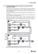
7RSURYLGHFXVWRPHUVPRUHDSSOLFDWLRQFKRLFHVWKH836ZLWKGXDOLQSXWFRQ¿JXUDWLRQVFDQ
have a hot standby redundancy function. If you use two UPSs and wish them to work in hot
standby redundancy mode, please connect the output of UPS1 to the bypass input of UPS 2.
Please see
Figure 3-28
.
For more information about the hot standby redundancy application, please contact service
personnel.
In normal condition, it is the UPS 2 inverter that supplies power to the critical loads. Both
UPS 1 & UPS 2 tri-color LEDs illuminate green.
When the UPS 2 inverter becomes abnormal, the UPS 2 will automatically transfer to
bypass mode and the UPS 1 inverter will supply power to the critical loads. Under such
circumstances, the UPS 1 tri-color LED illuminates green and the UPS 2 tri-color LED
illuminates yellow.
MAIN
LOAD
MAIN
1
2
BYPA.
Q1
Q2
Q4
Q3
Q5
Batteries
Rectifier
Inverter
Static Switch
Q1
Q2
Q4
Q3
Q5
Batteries
Rectifier
Inverter
Static Switch
Bypass Input
Terminals
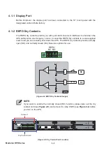
(Figure 3-28: Hot Standby Redundancy Diagram (only for Dual Input & at Least Two UPSs))
Содержание Modulon DPH series
Страница 26: ......
Страница 58: ......
Страница 168: ......
Страница 237: ...8 1 8 Optional Accessories 8 Optional Accessories...
Страница 240: ......
Страница 241: ...9 1 9 Maintenance Maintenance 9...
Страница 243: ...A1 1 Appendix 1 7HFKQLFDO 6SHFL FDWLRQV Technical 6SHFL FDWLRQV A1 A1...
Страница 246: ......
Страница 247: ...A2 1 Appendix 2 Warranty Warranty A2 A2...
Страница 250: ......

