5 - 4 0
Modulon DPH Series
2
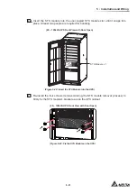
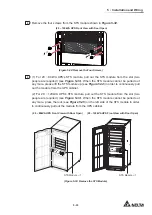
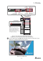
Use a screwdriver to remove the four screws from the power module shown in
Figure 5-45
.
S3
S4
BT3 BT4
USB
RS-232
P4
P5
P6
P2
BATT.
START
BATT.
START
P3
P4
PARALLEL
PARALLEL
(20 ~ 120kVA UPS Internal View with front Door Open
and Removal of the Power Module Slot’s Cover)
Power Module
(Figure 5-45: Remove the Four Screws)
3
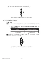
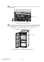
Pull out the power module from the slot (two people are required) (see
Figure 5-46
).
When the power module cannot be pulled out any more, lift up the power module
(see
Figure 5-47
) in order to continuously pull it out of the UPS cabinet.
INPUT
BREAKER
OUTPUT
BREAKER
BYPASS
BREAKER
MANUAL BYPASS
BREAKER
D
IS
P
L
A
Y
/C
O
N
S
O
L
E
E
M
S
RESE
T
GND
B A
GND
B A
MOD
BUS
BMS
DISPLAY
REPO
NC
NO
EXT. BATT
TEMP.
BT1 BT2
EXT.SWITCH
STATUS
S1
S2
S3
S4
BT3 BT4
O/P DRY
CONTACT
USB
RS-232
P1
P2
P3
P4
P5
P6
I/P DRY
CONTACT
P1
P2
BATT.
START
BATT.
START
P3
P4
PARALLEL
PARALLEL
(20 ~ 120kVA UPS Internal View with front Door Open)
Power Module
(Figure 5-46: Remove the Power Module from the UPS Cabinet)
Содержание Modulon DPH series
Страница 26: ......
Страница 58: ......
Страница 168: ......
Страница 237: ...8 1 8 Optional Accessories 8 Optional Accessories...
Страница 240: ......
Страница 241: ...9 1 9 Maintenance Maintenance 9...
Страница 243: ...A1 1 Appendix 1 7HFKQLFDO 6SHFL FDWLRQV Technical 6SHFL FDWLRQV A1 A1...
Страница 246: ......
Страница 247: ...A2 1 Appendix 2 Warranty Warranty A2 A2...
Страница 250: ......


