6 - 1 5
6
UPS Operation
7
When the UPS performs DC BUS discharging, each power module’s LED indicator
ÀDVKHVJUHHQ$IWHUGLVFKDUJLQJHDFKSRZHUPRGXOH¶V/('LQGLFDWRUZLOOEHRႇ
8
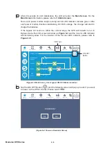
About three minutes later, the UPS will shut down, and the LCD and the tri-color
/('ZLOOEHRႇ
9
Switch
OFF
every external battery cabinet’s breaker (Q5).
y
From Manual Bypass Mode to Online Mode
WARNING:
1. For parallel units, please follow
6.2.3 Bypass Mode Start-up Procedures
WRWXUQRQHDFKSDUDOOHO836$IWHUFRQ¿UPLQJWKDWSDUDOOHORSHUDWLRQZRUNV
normally, follow the procedures below step by step.
2. For parallel units, ensure that every operation procedure mentioned below
is synchronized to all parallel UPSs.
)RUSDUDOOHODSSOLFDWLRQLI\RXMXVWZDQWWRRSHUDWHDVSHFL¿F836EXWQRWDOO
parallel ones, please contact service personnel.
1
Switch
ON
every external battery cabinet’s breaker (Q5).
2
Switch
ON
the Input Breaker (Q1), Bypass Breaker (Q2) and Output Breaker (Q4).
3
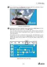
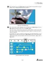
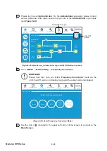
After you switch on the Input Breaker (Q1) and Bypass Breaker (Q2), each
auxiliary power card’s LED indicator will illuminate green and the following status
will occur simultaneously.
(1) The system and each power module will start initialization. After each power
module finishes initialization, each power module’s fans will start running,
each power module will start establishing DC BUS voltage and each power
module’s LED indicator will illuminate green.
(2) The parallel communication card’s LED indicator will illuminate red first
and then the card will start initialization. After initialization, the parallel
communication card’s LED indicator will illuminate green.
NOTE:
If you purchase an additional parallel communication card (optional)
and install it in the parallel communication card slot shown in
Figure 4-12
, the card’s LED indicator will illuminate red first and
then the card will start initialization. After initialization, the parallel
communication card’s LED indicator will illuminate yellow. For more
information, please refer to
4.1.7 Parallel Communication Card
.
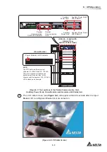
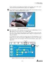
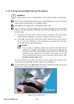
For the locations of the parallel communication card, auxiliary power cards, power
modules and associated LED indicators, please refer to
Figure 6-1
.
Содержание Modulon DPH series
Страница 26: ......
Страница 58: ......
Страница 168: ......
Страница 237: ...8 1 8 Optional Accessories 8 Optional Accessories...
Страница 240: ......
Страница 241: ...9 1 9 Maintenance Maintenance 9...
Страница 243: ...A1 1 Appendix 1 7HFKQLFDO 6SHFL FDWLRQV Technical 6SHFL FDWLRQV A1 A1...
Страница 246: ......
Страница 247: ...A2 1 Appendix 2 Warranty Warranty A2 A2...
Страница 250: ......

