3 - 1 5
3
Operation Modes
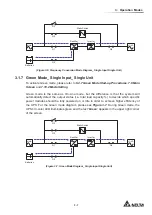
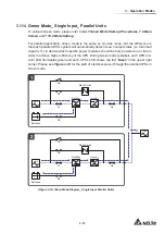
3.1.14 Green Mode_ Single Input_ Parallel Units
To activate Green mode, please refer to
6.2.7 Green Mode Start-up Procedures
,
7.6 Main
Screen
and
7.10.2 Mode Setting
.
)RUSDUDOOHODSSOLFDWLRQ*UHHQPRGHLVWKHVDPHDV2Q/LQHPRGHEXWWKHGLႇHUHQFHLV
that each parallel UPS’s system will automatically detect its own output status (i.e. total load
FDSDFLW\WRGHFLGHZKLFKVSHFL¿FSRZHUPRGXOHVVKRXOGEHIXOO\SRZHUHGRQRULGOHLQ
RUGHUWRDFKLHYHKLJKHUHႈFLHQF\RIWKH836'XULQJ*UHHQPRGHSDUDOOHOHDFK836¶VWUL
color LED illuminates green and each UPS’s LCD shows the text '
Green
' in the upper right
corner. Please see
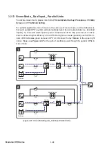
Figure 3-14
for the path of electrical power through the parallel UPSs in
Green mode.
MAIN
LOAD
MAIN
1
2
Q1
Q2
Q4
Q3
Batteries
Rectifier
Inverter
Static Switch
Q1
Q2
Q4
Q3
Batteries
Rectifier
Inverter
Static Switch
Q5
Q5
(Figure 3-14: Green Mode Diagram_ Single Input Parallel Units)
Содержание Modulon DPH series
Страница 26: ......
Страница 58: ......
Страница 168: ......
Страница 237: ...8 1 8 Optional Accessories 8 Optional Accessories...
Страница 240: ......
Страница 241: ...9 1 9 Maintenance Maintenance 9...
Страница 243: ...A1 1 Appendix 1 7HFKQLFDO 6SHFL FDWLRQV Technical 6SHFL FDWLRQV A1 A1...
Страница 246: ......
Страница 247: ...A2 1 Appendix 2 Warranty Warranty A2 A2...
Страница 250: ......

