4 - 1 5
4
Communication Interfaces
B. Bottom
Entry
1
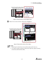
Open the UPS’s front door.
2
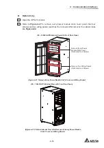
Refer to
Figure 4-21
to remove every power module slot’s cover (each has four
screws) and two wiring panels (each has four screws). After removal, the cabinet looks
like
Figure 4-22
.
INPUT
BREAKER
OUTPUT
BREAKER
BYPASS
BREAKER
MANUAL
BYPASS
BREAKER
(20 ~ 120kVA UPS Internal View with Front Door Open)
Remove Two Wiring Panels
(Each Has Four Screws)
Remove Every Power
Module Slot’s Cover
(Each Has Four Screws)
(Figure 4-21: Remove Every Power Module Slot’s Cover and Wiring Panels)
(20 ~ 120kVA UPS Internal View with Front Door Open)
(Figure 4-22: Cabinet Internal View after Removal of Every Power Module
Slot’s Cover and Wiring Panels)
Содержание Modulon DPH series
Страница 26: ......
Страница 58: ......
Страница 168: ......
Страница 237: ...8 1 8 Optional Accessories 8 Optional Accessories...
Страница 240: ......
Страница 241: ...9 1 9 Maintenance Maintenance 9...
Страница 243: ...A1 1 Appendix 1 7HFKQLFDO 6SHFL FDWLRQV Technical 6SHFL FDWLRQV A1 A1...
Страница 246: ......
Страница 247: ...A2 1 Appendix 2 Warranty Warranty A2 A2...
Страница 250: ......

