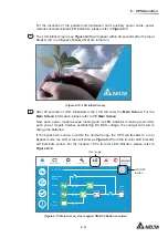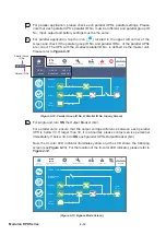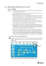
6 - 2
Modulon DPH Series
3UH6WDUWXS 3UH7XUQRႇ:DUQLQJVIRU6LQJOH8QLWDQG
Parallel Units
NOTE:
1. All unit No., UPS status, date, time, warning No., event No., load (%), battery
remaining time, user login, administrator login, etc. shown in the LCD diagrams
presented in
6. UPS Operation
are for reference only. Actual readings depend
on the operation of the UPS.
2. In this user manual, the meaning of Q1, Q2, Q3, Q4 and Q5 represents the
following.
Code
Meaning
Q1
Input Breaker
Q2
Bypass Breaker
Q3
Manual Bypass Breaker
Q4
Output Breaker
Q5
External Battery Cabinet’s Breaker
(The Q5 status shown on the LCD is always
ON by default. If you want to detect the status
of Q5, please refer to
7.10.6 Dry Contact
Setting
. )
3. Before operation, ensure that installation and wiring have been completely done
according to
5. Installation and Wiring
, and relevant instructions have been
followed.
4. Before operation, please refer to
2.8 Tri-color LED Indicator & Buzzer
and
7.
LCD Display & Settings
.
5. (1) The setting of the
2Q2ႇ%XWWRQ$FFHVV
is set as '
Any User
' for all the
ON/ OFF Button
(
) presented in this user manual.
(2) If you want to change the access setting for the
ON/ OFF Button
(
),
please go to
SETUP
ĺ
General Setting
ĺ
User
ĺ
On/ OFF Button Access
.
For relevant information, please refer to
7.10.7 General Setting
.
Single Unit
y
Pre Start-up Warnings for Single Unit
1. Make sure that all the breakers, including every external battery cabinet’s breaker
(Q5), are turned to the
OFF
position.
0DNHVXUHWKDWWKH836¶VYROWDJHGLႇHUHQFHEHWZHHQWKH1HXWUDO1DQG*URXQG
)
is < 3V.
Содержание Modulon DPH series
Страница 26: ......
Страница 58: ......
Страница 168: ......
Страница 237: ...8 1 8 Optional Accessories 8 Optional Accessories...
Страница 240: ......
Страница 241: ...9 1 9 Maintenance Maintenance 9...
Страница 243: ...A1 1 Appendix 1 7HFKQLFDO 6SHFL FDWLRQV Technical 6SHFL FDWLRQV A1 A1...
Страница 246: ......
Страница 247: ...A2 1 Appendix 2 Warranty Warranty A2 A2...
Страница 250: ......


