5 - 4 1
5
Installation and Wiring
INPUT BREAKER
૿ҵލ૨֘
OUTPUT BREAKER
૿ӟލ૨֘
BYPASS BREAKER
ޒ૨ލ૨֘
MANUAL BYPASS BREAKER
۴Ԉғޒ૨ލ૨֘
D
IS
P
L
A
Y
/C
O
N
S
O
L
E
E
M
S
RESE
T
GND
B A
GND
B A
MOD
BUS
BMS
DISPLAY
REPO
NC
NO
EXT. BATT
TEMP.
BT1 BT2
EXT.SWITCH
STATUS
S1
S2
S3
S4
BT3 BT4
O/P DRY
CONTACT
USB
RS-232
P1
P2
P3
P4
P5
P6
I/P DRY
CONTACT
P1
P2
BATT.
START
BATT.
START
P3
P4
PARALLEL
PARALLEL
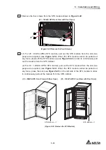
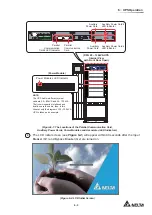
(20 ~ 120kVA UPS Internal View with front Door Open)
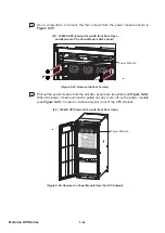
Lift up the
Power Module
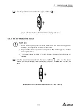
(Figure 5-47: Lift up the Power Module)
5.8.3 Power Module’s LED Indicator
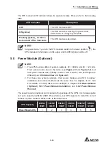
The power module’s LED indicator shows its operation status. Please refer to the following
table.
LED Indicator
(Figure 5-48: Power Module’s LED Indicator)
LED Indicator
Description
OFF
The power module is OFF.
ON (green)
1. The power module is running in online mode
or in battery mode.
2. The power module’s inverter starts up.
3. The power module’s PFC starts up.
Содержание Modulon DPH series
Страница 26: ......
Страница 58: ......
Страница 168: ......
Страница 237: ...8 1 8 Optional Accessories 8 Optional Accessories...
Страница 240: ......
Страница 241: ...9 1 9 Maintenance Maintenance 9...
Страница 243: ...A1 1 Appendix 1 7HFKQLFDO 6SHFL FDWLRQV Technical 6SHFL FDWLRQV A1 A1...
Страница 246: ......
Страница 247: ...A2 1 Appendix 2 Warranty Warranty A2 A2...
Страница 250: ......

