


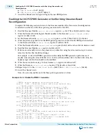


Figure 16-10: Transceiver Reconfiguration Controller Interface Bundles
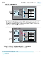
The following figure shows a design with two transceiver PHY IP core instances, each with four channels.
For this design you would enter 16 for the Number of reconfiguration interfaces and 8, 8 for the
Optional interface grouping parameter.
Depending upon the transceiver PHY IP core and the parameters specified, the number of reconfigura‐
tion interfaces varies. For a single-channel, RX-only transceiver instance, there is a single reconfiguration
interface. One reconfiguration interface is created for a single-channel Low Latency PHY setup as a RX
only channel. Two reconfiguration interfaces are created for a single-channel Custom PHY setup as a
duplex channel. The reconfiguration interfaces do not appear as separate buses, but as a single bus of
concatenated reconfiguration interfaces, that grows linearly with the number of reconfiguration
interfaces.
Although you must create a separate logical reconfiguration interface for each PHY IP core instance,
when the Quartus II software compiles your design, it reduces original number of logical interfaces by
merging them. Allowing the Quartus II software to merge reconfiguration interfaces gives the Fitter more
flexibility in placing transceiver channels. However, the logical channel number remains the same.
Note: You cannot use SignalTap
™
to observe the reconfiguration interfaces.
You do not have to assign numbers to the reconfiguration interfaces. The logical interface numbering is
determined by the order of the interfaces in the connection between the transceiver PHY IP and the
Transceiver Reconfiguration Controller.
16-52
Understanding Logical Channel Numbering
UG-01080
2015.01.19
Altera Corporation
Transceiver Reconfiguration Controller IP Core Overview
Send Feedback


