


Example 11-4: Total Delay Uncertainty
Round trip delay estimates are subject to process, voltage, and temperature (PVT) variation.
t
RXCL K _P hase_detector_uncertainty
= 2 × max (<t
G L L _phase_step
>, <t
C D R_t o_GPLL_ jitter
>) + µ t
SU
+ µ t
H
t
Round_trip_uncertainty
= <t
RX_CLK_Phase_detector_uncertainty
+ t
>
+<t
feedback_variation
> + <t
TX_tco_ variation
> + <t
IO ->R X d eser_delay_variation
>
+ <t
PLL_multicycle_jitter
> + <t
offset_un certainty
>
GPLL->CMU PLL_variation
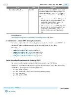
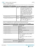
Table 11-2: TX PCS Total Latency
This table shows the total latency through the TX PCS in parallel clock cycles with the byte serializer/deserializer
turned off. The TX compensation FIFO is in register mode.
PCS Datapath Width
TX Phase
Comp FIFO
Serializer
8B/10B
Bitslip (
tx_std_
bitslipboundar-
yselect
)
Total TX Parallel
Clock Cycles
Byte Serializer/Deserializer Turned Off
8 bits
1.0
1.0
1.0
0
3.0
16 bits
1.0
1.0
1.0
0
3.0
Byte Serializer/Deserializer Turned On
16 bits
1.0
0.5
0.5
0
2.0
32 bits
1.0
0.5
0.5
0
2.0
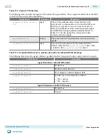
Table 11-3: RX PCS Total Latency
The RX compensation FIFO is in register mode. When the byte serializer/deserializer in turned on, the latency
through is function depends on the location of the alignment pattern. When the alignment pattern is in the upper
symbol, the delay is 0.5 cycles. When the alignment pattern is in the lower symbol, the delay is 1.0 cycles.
PCS Datapath Width
RX Phase
Comp FIFO
Byte
Ordering
Deserial‐
izer
8B/10B
Word
Aligner
(10)(9)
Total RX Parallel
Clock Cycles
(9)(10)
Byte Serializer/Deserializer Turned Off
8 bits
1.0
1.0
1.0
1.0
4.0
8.0
(8)
This latency is calculated assuming that the optional
tx_std_bitslipboundaryselect
is set to zero. Add
one UI of latency per value of this port. For example, if
tx_std_bitslipboundaryselect
is set to one, add
one UI of latency to the total.
(9)
When the word aligner is in manual mode, and the byte deserializer is turned off, add x UI of latency to the
total latency if
rx_std_bitslipboundaryselect
is outputting x. For constant RX + TX latency, set
tx_std_bitslipboundaryselect
= 5’d9 –
rx_std_bitslipboundaryselect
.
(10)
When the word aligner is in manual mode, and the byte serializer is turned on, add (19-x) UI of latency to
the total latency if
rx_std_bitslipboundaryselect
is outputting x. For constant RX + TX latency, set
tx_std_bitslipboundaryselect
=
rx_std_bitslipboundaryselect
.
11-6
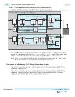
Deterministic Latency PHY Delay Estimation Logic
UG-01080
2015.01.19
Altera Corporation
Deterministic Latency PHY IP Core
Send Feedback


