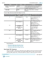
Name
Value
Description
Number of reference clocks
1-5
Specifies the number of input reference
clocks. More than one reference clock may be
required if your design reconfigures channels
to run at multiple frequencies.
Main TX PLL logical index
0-3
Specifies the index for the TX PLL that
should be instantiated at startup. Logical
index 0 corresponds to TX PLL0, and so on.
CDR PLL input clock source
0-3
Specifies the index for the CDR PLL input
clock that should be instantiated at startup.
Logical index 0 corresponds to input clock 0
and so on.
TX PLL (0-3)
PLL Type
CMU
ATX
Specifies the PLL type.
PLL base data rate
1 × Lane rate
2 × Lane rate
4 × Lane rate
Specifies Base data rate.
Reference clock frequency
Variable
Specifies the frequency of the PLL input
reference clock. The PLL must generate an
output frequency that equals the Base data
rate/2. You can use any Input clock
frequency that allows the PLLs to generate
this output frequency.
Selected reference clock source
0-4
Specifies the index of the input clock for this
TX PLL. Logical index 0 corresponds to input
clock 0 and so on.
Channel Interface
UG-01080
2015.01.19
PLL Reconfiguration Parameters
9-15
Custom PHY IP Core
Altera Corporation
Send Feedback


