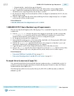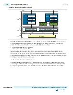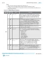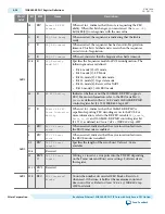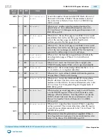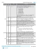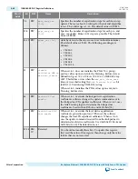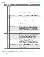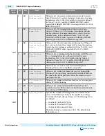
Table 4-16: Embedded Processor Interface Signals
Signal Name
Direction
Description
upi_mode_en
Input
When asserted, enables embedded processor mode.
upi_adj[1:0]
Input
Selects the active tap. The following encodings are
defined:
• 2'b01: Main tap
• 2'b10: Post
-
tap
• 2'b11: Pre
-
tap
upi_inc
Input
When asserted, sends the increment command.
upi_dec
Input
When asserted, sends the decrement command.
upi_pre
Input
When asserted, sends the preset command.
upi_init
Input
When asserted, sends the initialize command.
upi_st_bert
Input
When asserted, starts the BER timer.
upi_train_err
Input
When asserted, indicates a training error.
upi_rx_trained
Input
When asserted, the local RX interface is trained.
upo_enable
Output
When asserted, indicates that the 10GBASE
-
KR
PHY IP Core is ready to receive commands from
the embedded processor.
upo_frame_lock
Output
When asserted, indicates the receiver has achieved
training frame lock.
upo_cm_done
Output
When asserted, indicates the master state machine
handshake is complete.
upo_bert_done
Output
When asserted, indicates the BER timer is at its
maximum count.
upo_ber_cnt[ <w>-1:0]
Output
Records the BER count.
upo_ber_max
Output
When asserted, the BER counter has rolled over.
upo_coef_max
Output
When asserted, indicates that the remote
coefficients are at their maximum or minimum
values.
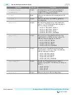
Dynamic Reconfiguration Interface Signals
You can use the dynamic reconfiguration interface signals to dynamically change between 1G,10G data
rates and AN or LT mode. These signals also used to update TX coefficients during Link Training..
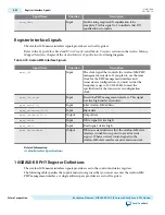
Table 4-17: Dynamic Reconfiguration Interface Signals
Signal Name
Direction
Description
reconfig_to_xcvr
[(<n>70-1):0]
Input
Reconfiguration signals from the Reconfiguration
Design Example.
<n>
grows linearly with the
number of reconfiguration interfaces.
UG-01080
2015.01.19
Dynamic Reconfiguration Interface Signals
4-29
Backplane Ethernet 10GBASE-KR PHY IP Core with Early Access FEC Option
Altera Corporation
Send Feedback

