8. Generate a fractional PLL to create the 156.25 MHz XGMII clock from the 10G reference clock.
9. Instantiate the PHY in your design based on the required number of channels.
10.To complete the system, connect all the blocks.
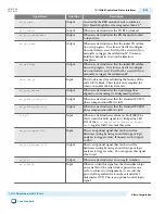
Dynamic Reconfiguration Interface Signals
You can use the dynamic reconfiguration interface signals to dynamically change between 1G,10G data
rates and AN or LT mode. These signals also used to update TX coefficients during Link Training..
Table 5-17: Dynamic Reconfiguration Interface Signals
Signal Name
Direction
Description
reconfig_to_xcvr
[(<n>70-1):0]
Input
Reconfiguration signals from the Reconfiguration
Design Example.
<n>
grows linearly with the
number of reconfiguration interfaces.
reconfig_from_xcvr
[(<n>46-1):0]
Output
Reconfiguration signals to the Reconfiguration
Design Example.
<n>
grows linearly with the
number of reconfiguration interfaces.
rc_busy
Input
When asserted, indicates that reconfiguration is in
progress.
lt_start_rc
Output
When asserted, starts the TX PMA equalization
reconfiguration.
main_rc[5:0]
Output
The main TX equalization tap value which is the
same as V
OD
. The following example mappings to
the V
OD
settings are defined:
• 6'b111111: FIR_MAIN_12P6MA
• 6'b111110: FIR_MAIN_12P4MA
• 6'b000001: FIR_MAIN_P2MA
• 6'b000000: FIR_MAIN_DISABLED
post_rc[4:0]
Output
The post
-
cursor TX equalization tap value. This
signal translates to the first post-tap settings. The
following example mappings are defined:
• 5'b11111: FIR_1PT_6P2MA
• 5'b11110: FIR_1PT_6P0MA
• 5'b00001: FIR_1PT_P2MA
• 5'b00000: FIR_1PT_DISABLED
pre_rc[3:0]
Output
The pre
-
cursor TX equalization tap value. This
signal translates to pre-tap settings. The following
example mappings are defined:
• 4'b1111: FIR_PRE_3P0MA
• 4'b1110: FIR_PRE_P28MA
• 4'b0001: FIR_PRE_P2MA
• 4'b0000: FIR_PRE_DISABLED
UG-01080
2015.01.19
Dynamic Reconfiguration Interface Signals
5-25
1G/10 Gbps Ethernet PHY IP Core
Altera Corporation
Send Feedback


