PHY for PCIe (PIPE) Clocks
This section describes the clock ports.
Table 8-6: Clock Ports
Signal Name
Direction
Description
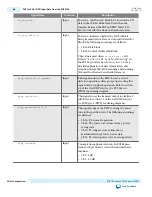
pll_ref_clk
Input
This is the 100 MHz input reference clock source for the
PHY TX and RX PLL. You can optionally provide a 125
MHz input reference clock by setting the PLL reference
clock frequency parameter to 125 MHz as described in
PHY IP Core for PCI Express General Options.
fixedclk
Input
A 100 MHz or 125 MHz clock used for the receiver detect
circuitry. This clock can be derived from
pll_ref_clk
.
pipe_pclk
Output
Generated in the PMA and driven to the MAC PHY
interface. All data and status signals are synchronous to
pipe_pclk
. This clock has the following frequencies:
• Gen1: 62.5 MHz
• Gen2:125 MHz
• Gen3: 250 MHz
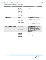
The following table lists the
pipe_pclk
frequencies for all available PCS interface widths. Doubling the
FPGA transceiver width haves the required frequency.
Table 8-7: pipe_pclk Frequencies
Capability
FPGA Transceiver Width
Gen1
Gen2
Gen3
Gen1 only
8 bits
250 MHz
—
—
16 bits
125 MHz
—
—
Gen2 capable
16 bits
125 MHz
250 MHz
—
Gen3 capable
32 bits
62.5 MHz
125 MHz
250 MHz
PHY for PCIe (PIPE) Clock SDC Timing Constraints for Gen3 Designs
For Gen3 designs, you must add the following timing constraints to force Timequest to analyze the design
at Gen1, Gen2 and Gen3 data rates. Include these constraints in your top-level SDC file for the project.
Add the following command to force Timequest analysis at 250 MHz.
create_generated_clock -name clk_g3 -source [get_ports {pll_refclk}] \
-divide_by 2 -multiply_by 5 -duty_cycle 50 -phase 0 -offset 0 [get_nets
{*pipe_nr_inst|transceiver_core|inst_sv_xcvr_native|inst_sv_pcs|\
|ch[*].inst_sv_pcs_ch|inst_sv_hssi_tx_pld_pcs_interface|pld8gtxclkout}] -add
UG-01080
2015.01.19
PHY for PCIe (PIPE) Clocks
8-13
PHY IP Core for PCI Express (PIPE)
Altera Corporation
Send Feedback


