


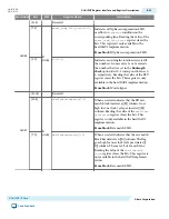
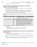


Figure 6-8: Clock Inputs and Outputs for IP Core with Hard PCS
XAUI Hard IP Core
4 x 3.125 Gbps serial
Hard PCS
tx_coreclk
rx_cruclk
pll_inclk
coreclkout
xgmii_rx_clk
xgmii_tx_clk
pll_ref_clk
phy_mgmt_clk
4
4
PMA
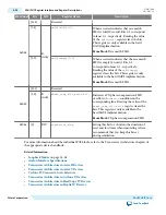
Figure 6-9: Clock Inputs and Outputs for IP Core with Soft PCS
XAUI Soft IP Core
4 x 3.125 Gbps serial
xgmii_rx_clk
xgmii_tx_clk
pll_ref_clk
phy_mgmt_clk
4
4
Soft PCS
pma_pll_inclk
pma_tx_clkout
tx_clkout
pma_rx_clkout
pll_ref_clk
sysclk
PMA
rx_recovered_clk
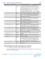
Table 6-10: Optional Clock and Reset Signals
Signal Name
Direction
Description
pll_ref_clk
Input
This is a 156.25 MHz reference clock that is used by the
TX PLL and CDR logic.
rx_analogreset
Input
This signal resets the analog CDR and deserializer logic
in the RX channel. It is available only for the hard IP
implementation.
rx_digitalreset
Input
PCS RX digital reset signal. It is available only for the
hard IP implementation.
tx_digitalreset
Input
PCS TX digital reset signal. If your design includes
bonded TX PCS channels, refer to Timing Constraints
for Reset Signals when Using Bonded PCS Channels for
a SDC constraint you must include in your design. It is
available only for the hard IP implementation.
6-14
XAUI PHY Clocks, Reset, and Powerdown Interfaces
UG-01080
2015.01.19
Altera Corporation
XAUI PHY IP Core
Send Feedback


