


Signal Name
Direction
Description
pll_ref_clk
Input
Reference clock for the PHY PLLs. The
frequency range is 60–700 MHz.
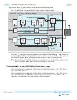
Optional Reset Control and Status Interface
The following table describes the signals in the optional reset control and status interface. These signals
are available if you do not enable the embedded reset controller. For more information including timing
diagrams, refer to
Transceiver Reset Control in Stratix V Devices
in volume 2 of the Stratix V Device
Handbook.
Table 10-11: Avalon-ST RX Interface
Signal Name
Direction
Description
pll_powerdown
Input
When asserted, resets the TX PLL.
tx_digitalreset[<n>-1:0]
Input
When asserted, reset all blocks in the TX PCS. If
your design includes bonded TX PCS channels,
refer to
Timing Constraints for Reset Signals
when
Using Bonded PCS Channels for a SDC
constraint you must include in your design.
tx_analogreset[<n>-1:0]
Input
When asserted, resets all blocks in the TX PMA.
tx_cal_busy[<n>-1:0]
Output
When asserted, indicates that the initial TX
calibration is in progress. It is also asserted if
reconfiguration controller is reset. It will not be
asserted if you manually re-trigger the calibration
IP. You must hold the channel in reset until
calibration completes.
rx_digitalreset[<n>-1:0]
Input
When asserted, resets the RX PCS.
rx_analogreset[<n>-1:0]
Input
When asserted, resets the RX CDR.
rx_cal_busy[<n>-1:0]
Output
When asserted, indicates that the initial RX
calibration is in progress. It is also asserted if
reconfiguration controller is reset. It will not be
asserted if you manually re-trigger the calibration
IP.
Related Information
Timing Constraints for Bonded PCS and PMA Channels
on page 17-10
10-16
Optional Reset Control and Status Interface
UG-01080
2015.01.19
Altera Corporation
Low Latency PHY IP Core
Send Feedback


