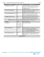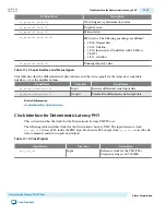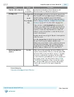
Word Addr
Bits
R/W
Register Name
Description
0x044
[31:0]
RW
reset_fine_control
You can use the
reset_fine_
control
register to create your own
reset sequence. In manual mode,
only the TX reset occurs automati‐
cally at power on and when the
phy_
mgmt_clk_reset
is asserted. When
pma_rx_setlocktodata
or
pma_rx_
setlocktodata
is set, the transceiver
PHY is placed in manual mode.
[31:4,0] RW
Reserved
It is safe to write 0s to reserved bits.
[3]
RW
reset_rx_digital
Writing a 1 causes the internal RX
digital reset signal to be asserted,
resetting the RX digital channels
enabled in
reset_ch_bitmask
. You
must write a 0 to clear the reset
condition.
[2]
RW
reset_rx_analog
Writing a 1 causes the internal RX
analog reset signal to be asserted,
resetting the RX analog logic of all
channels enabled in
reset_ch_
bitmask
. You must write a 0 to clear
the reset condition.
[1]
RW
reset_tx_digital
Writing a 1 causes the internal TX
digital reset signal to be asserted,
resetting all channels enabled in
reset_ch_bitmask
. You must write
a 0 to clear the reset condition.
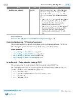
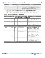
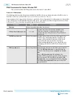
PMA Control and Status Registers
0x061
[31:0]
RW
phy _ serial _ loopback
Writing a 1 to channel <
n
> puts
channel <
n
> in serial loopback
mode. For information about pre
-
or
post
-
CDR serial loopback modes,
refer to Loopback Modes.
0x064
[31:0]
RW
pma_rx_set_locktodata
When set, programs the RX CDR
PLL to lock to the incoming data. Bit
<
n
> corresponds to channel <
n
>.
0x065
[31:0]
RW
pma_rx_set_locktoref
When set, programs the RX CDR
PLL to lock to the reference clock. Bit
<
n
> corresponds to channel <
n
>.
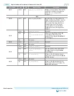
0x066
[31:0]
RO
pma_rx_is_lockedtodata
When asserted, indicates that the RX
CDR PLL is locked to the RX data,
and that the RX CDR has changed
from LTR to LTD mode. Bit <n>
corresponds to channel <n>.
UG-01080
2015.01.19
Register Interface and Descriptions for Deterministic Latency PHY
11-25
Deterministic Latency PHY IP Core
Altera Corporation
Send Feedback


