


Related Information
•
Transceiver Reset Control in Stratix V Devices
•
Transceiver Reset Control and Power-Down in Arria V Devices
•
Transceiver Reset Control and Power Down in Cyclone V Devices
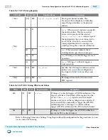
Transceiver Reconfiguration Controller PLL Reconfiguration Registers
Lists the PLL reconfiguration registers that you can access using Avalon-MM read and write commands
on reconfiguration management interface.
Note: All undefined register bits are reserved.
Table 16-19: PLL Reconfiguration Registers
Reconfig Addr
Bits
R/W
Register Name
Description
7’h40
[9:0] RW
logical channel number
The logical channel number. Must be
specified when performing dynamic
updates. The Transceiver Reconfiguration
Controller maps the logical address to the
physical address.
When reconfiguring the reference clock
for the TX PLL you must specify the PLL's
logical channel number. When reconfi‐
guring the reference clock for the CDR you
must specify the channel's logical channel
number.
7’h42
[9]
R
control and status
When asserted, indicates an error. This bit
is asserted if any of the following
conditions occur:
• The channel address is invalid.
• The PHY address is invalid.
• The address offset is invalid.
[8]
R
MIF Busy
. When asserted, indicates that a
reconfiguration operation is in progress.
[1]
W
Read
. Writing a 1 to this bit triggers a read
operation.
[0]
W
Write
. Writing a 1 to this bit triggers a
write operation.
7’h43
[3:0] RW
pll_offset
Specifies the 4-bit register address used for
indirect to the PLL registers on the reconfi‐
guration bus. Refer to Table 16–21 for
offsets and values.
16-30
Transceiver Reconfiguration Controller PLL Reconfiguration Registers
UG-01080
2015.01.19
Altera Corporation
Transceiver Reconfiguration Controller IP Core Overview
Send Feedback


