


4-297
21-09 Maximum frequency for position control
Maximum output frequency when moving to the next position. The position control function uses deceleration time
1 (00-15).
In the SV control mode, multi-function digital input terminals (03-00 to 03-07) can be used to select the position.
See table 4.4.19.
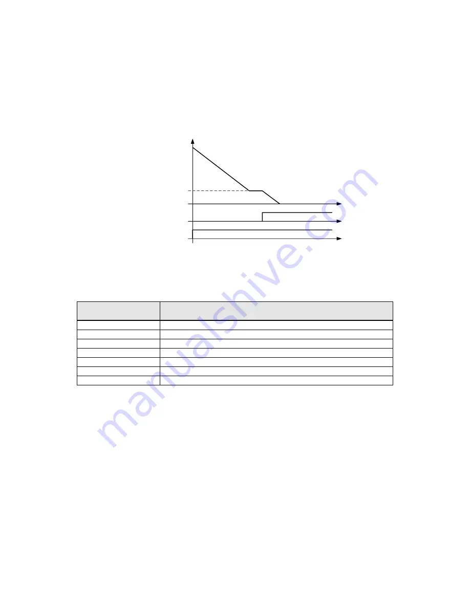
Run
DI (Zero Servo)
Fmin (01-08)
Output
Figure 4.3.129 Zero-servo positioning
Table 4.4.19 Multi-position positioning function setting
Digital Input setting
03-00~03-07
Function
02
Multi-speed/position setting command 1
03
Multi-speed/position setting command 2
04
Multi-speed/position setting command 3
05
Multi-speed/position setting command 4
46
Zero-Servo command
51
Select between speed control and position control
52
Position command enable
Zero-servo positioning function
(Zero-Srvo):
When the output frequency falls below Fmin and the zero-servo input is active, the position is locked in and the
inverter enters zero-servo positioning mode (Zero-Srvo). Positioning command PosRef is origin, as shown in
figure 4.4.129.
Refer to parameter 11-49 and 11-50 for zero-servo gain and zero-servo count and parameter 20-02 and 20-03 to
setup the speed regulator function.
Multi-position function
(MultiPosRef):
Parameter 21-42 is set to 0 and the speed is lower than the lowest frequency so the inverter will enter into the
position mode. If input multi-speed and multi-position command switch (DI is set to 51) in the zero-srvo mode,
multi-speed command 1~4 is transformed to multi-position command 1~4 and the origin of zero-srvo mode has
17-section position. Refer to Fig.4.4.130.


