


4-298
Spindle Positioning Function
(Z-phase locked function)
Parameter 21-42 is set to 1 and the speed is lower than the lowest frequency so the inverter will enter into the
position mode when Z-phase signal appears. The origin is positioned in z phase signal and the setting value of
parameter 21-43. It can be also coupled with multi-position function.
Z phase bias value of monitoring parameter 12-78 will display the bias between Z phase and the current position.
User can rotate the motor at one cycle depending on the rotation direction. Z phase bias value of parameter 12-78
is the differential value between steering position Z point after capturing the position of Z point. Make the value of
12-78 input the offset angle of parameter 21-43 after the position is confirmed. Then the origin is positioned at Z
phase the setting value of parameter 21-43.
Note
: If the motor is just at power on and does not pass the Z point, parameter 12-78 will display 9999.
Position control:
-
Activate Run command (RUN)
-
Activate Zero-Servo command (Zero-Srvo)
-
Activate Position enable command (MultiPosEn)
-
Select a position with the multi-function digital inputs (PosRef)
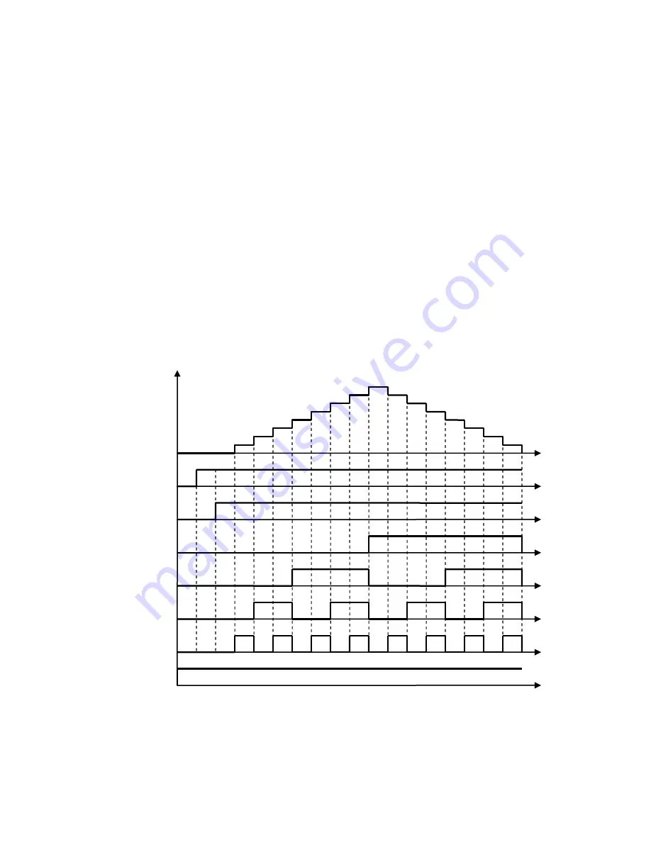
Refer to figure 4.4.130.
Figure 4.4.130 Multi-positioning logic diagram
Refer to parameter 20-28 to set PG motor direction.
A position is defined by the number of rotations plus the number of pulses.
When multi-position function is used, position command enable (Multi Pos. Enable, DI is set to 52) is required to
be ON so the inverter can receive the external position command. Refer to Fig. 4.4.131.
Run
Zero-Srvo
S4
S1
S3
S2
MultiPosRefEn
PosRef 0~15


