Rostock MAX v2 Assembly Guide
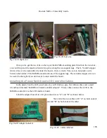
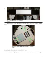
Once you've got the two tabs on the top of the RAMBo mounting plate fitted into the two slots,
you can lift up and the mount will slide into place along the two support legs. The X, Y and Z stepper
motor wires can be routed directly under the board – there
is
room. Take care to not pinch a wire
between the bottom of the RAMBo mount and one of the support legs. The extruder stepper wire can
be routed to the right if you don't want to run it under the board.
Installing the Power Switch and LCD Controller Cables
In the plastic box the LCD panel came in, you'll find two gray, flat ribbon cables and a small
circuit board marked “RAMBo to SmartController adapter”. These cables connect the LCD to the
RAMBo controller via the LCD interface board.
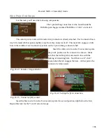
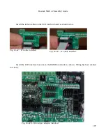
Label the adapter board's two 10 pin connectors as “A” and “B” as shown below.
Next, label the two cables with “A” on both ends of
one and “B” on both ends of the other.
196
Fig. 16-38: Right slot.
Fig. 16-39: Left slot.
Fig. 16-40: Adapter labeled.
Fig. 16-41: Cables labeled.
Summary of Contents for Rostock MAX v2
Page 25: ...Rostock MAX v2 Assembly Guide Melamine Parts Sheet 1 25 ...
Page 26: ...Rostock MAX v2 Assembly Guide Melamine Parts Sheet 2 Melamine Parts Sheet 3 26 ...
Page 27: ...Rostock MAX v2 Assembly Guide Melamine Parts Sheet 4 27 ...
Page 171: ...Rostock MAX v2 Assembly Guide 171 Fig 14 8 Spool holder support installed ...


