Rostock MAX v2 Assembly Guide
Preparing the Power Supply
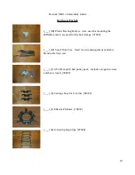
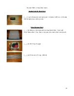
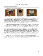
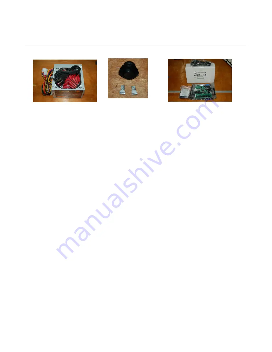
For this task, you'll need these components:
Your Rostock MAX v2 uses a standard ATX computer power supply to provide power to the
RAMBo controller, the Onyx heated bed and the hot-end. All of these components require 12V DC.
The 12V wires on an ATX power supply are yellow. You’ll need four of these for the heated bed
power, and one each for the hot-end and motors. Each yellow wire must be accompanied by a ground
(black) wire, so you'll need six black wires in addition to the six yellow.
The heated bed terminal requires four wires because the Onyx draws a lot of power – more than
a single wire can supply. Think of each wire as a water hose. For a given diameter of hose, you can
only deliver so much water at a time. However, if you use FOUR hoses, you can deliver four times the
volume. In our case “volume” is “amperes” (the “water pressure” is volts). So using four wires gives
us four times the amps that a single wire can deliver. Understand that if you try to draw too much
through a single wire, the electrons inside the wire basically get into a fight with each other, all trying
to escape through the same tiny hole at once. All this combat generates heat. As the heat increases, the
ability of the wire to carry this current decreases. The hotter it gets, the worse the problem gets until
something gives up. Usually the “give up” point happens with a melted connector and a dead RAMBo.
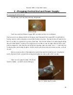
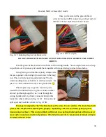
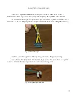
The first thing we're going to do is locate the power-on wires that are on the main ATX
connector. We're looking for a green wire and a matching black wire as shown. [By shorting the green
& black wires together via a switch, it causes the ATX power supply to turn on.]
33
Power Switch
Pack
RAMBo Box
Power Supply
Summary of Contents for Rostock MAX v2
Page 25: ...Rostock MAX v2 Assembly Guide Melamine Parts Sheet 1 25 ...
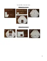
Page 26: ...Rostock MAX v2 Assembly Guide Melamine Parts Sheet 2 Melamine Parts Sheet 3 26 ...
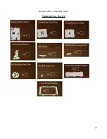
Page 27: ...Rostock MAX v2 Assembly Guide Melamine Parts Sheet 4 27 ...
Page 171: ...Rostock MAX v2 Assembly Guide 171 Fig 14 8 Spool holder support installed ...

