Rostock MAX v2 Assembly Guide
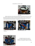
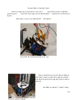
Make sure that the hot end is turned such that the sides of the PEEK fan shroud can go to either
side of the hot end body, but not trap a wire between the shroud and the hot end. You do NOT want
wires jammed against the hot end by the fan shroud! When you slide the fan shroud into place, the
“arms” should come in full contact with the 1” aluminum spacers to either side.
Now tighten down the two screws you
loosened in order to install the fan and attach the
fan leads to the knotted pair of 26ga wires coming
254
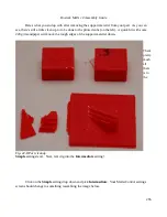
Fig. 20-26: Loose screws. (But you knew
that, right?)
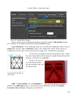
Fig. 20-27: Side view of fan shroud
installation.
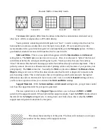
Fig. 20-28: Another side view...
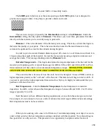
Fig. 20-29: What is it with all these angles?
Summary of Contents for Rostock MAX v2
Page 25: ...Rostock MAX v2 Assembly Guide Melamine Parts Sheet 1 25 ...
Page 26: ...Rostock MAX v2 Assembly Guide Melamine Parts Sheet 2 Melamine Parts Sheet 3 26 ...
Page 27: ...Rostock MAX v2 Assembly Guide Melamine Parts Sheet 4 27 ...
Page 171: ...Rostock MAX v2 Assembly Guide 171 Fig 14 8 Spool holder support installed ...


