Rostock MAX v2 Assembly Guide
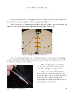
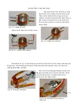
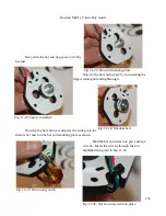
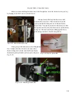
You'll note that the wires in Fig. 10-29 bend
away from the black & white end stop wires on the far
right. This is done on purpose. This is done in order to
keep the motor wires way from the two small end-stop
wires. If they're run in close parallel with one another, they can pick up current from the stepper motor
and cause false end-stop triggers to be reported. If that happens, the printer does very, very odd things.
Checkpoint Video #14:
11 – Installing the Hot End and Bowden Tube
Preparing the Hot End Wiring
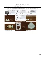
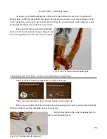
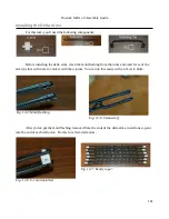
For this task, you'll need the short length of heat shrink tubing and the 3/8” Black, Expandable
Mesh Loom.
148
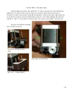
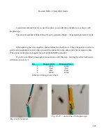
Fig. 10-28: All four wires done!
Fig. 10-29: Completed extruder wiring.
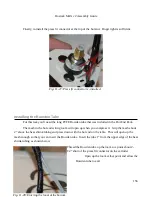
Mesh wiring loom and heat shrink tubing.
Summary of Contents for Rostock MAX v2
Page 25: ...Rostock MAX v2 Assembly Guide Melamine Parts Sheet 1 25 ...
Page 26: ...Rostock MAX v2 Assembly Guide Melamine Parts Sheet 2 Melamine Parts Sheet 3 26 ...
Page 27: ...Rostock MAX v2 Assembly Guide Melamine Parts Sheet 4 27 ...
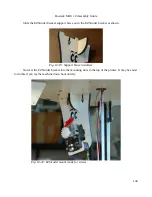
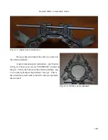
Page 171: ...Rostock MAX v2 Assembly Guide 171 Fig 14 8 Spool holder support installed ...

