Rostock MAX v2 Assembly Guide
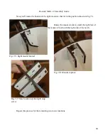
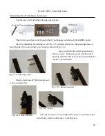
Now you'll rotate the bottom of the right mount so that it's in the position shown in Fig 7.5.
Rotate the mount clockwise until the right face of
the mount is flush with the right side of the notch.
Repeat this process for the remaining two tower locations.
94
Fig. 7-5: Right mount rotated.
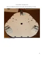
Fig. 7-6: Mounts in place.
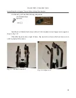
Fig. 7-7: Note location of the depth stop
screw.
Summary of Contents for Rostock MAX v2
Page 25: ...Rostock MAX v2 Assembly Guide Melamine Parts Sheet 1 25 ...
Page 26: ...Rostock MAX v2 Assembly Guide Melamine Parts Sheet 2 Melamine Parts Sheet 3 26 ...
Page 27: ...Rostock MAX v2 Assembly Guide Melamine Parts Sheet 4 27 ...
Page 171: ...Rostock MAX v2 Assembly Guide 171 Fig 14 8 Spool holder support installed ...


