Rostock MAX v2 Assembly Guide
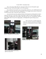
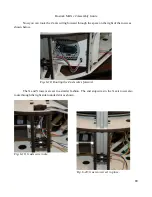
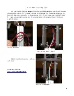
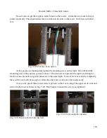
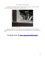
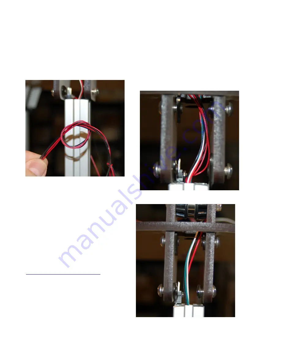
The Y axis carries the wires needed to drive the extruder stepper motor as well as the two pairs
of wires needed to power the PEEK and layer fans. Go ahead and route the stepper motor wires up
through the hole just as you did for the end stop wires. Since the wire gauge is very similar between
the stepper wires and the fan wires, knot the fan wires loosely before routing them. It'll help you
identify them later.
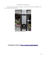
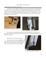
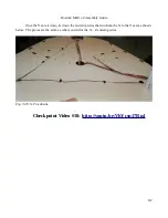
Finally, route the Z axis wires as shown
on the right.
Checkpoint Video #8:
102
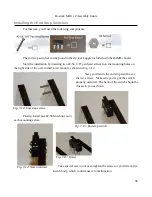
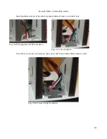
Fig. 7-25: Fan wires.
Fig. 7-26: Y axis wires routed.
Fig. 7-27: Z Axis wires.
Summary of Contents for Rostock MAX v2
Page 25: ...Rostock MAX v2 Assembly Guide Melamine Parts Sheet 1 25 ...
Page 26: ...Rostock MAX v2 Assembly Guide Melamine Parts Sheet 2 Melamine Parts Sheet 3 26 ...
Page 27: ...Rostock MAX v2 Assembly Guide Melamine Parts Sheet 4 27 ...
Page 171: ...Rostock MAX v2 Assembly Guide 171 Fig 14 8 Spool holder support installed ...

