Rostock MAX v2 Assembly Guide
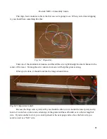
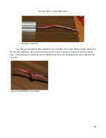
aluminum inner jacket. For this task we'll only be using the red & black wires. The other two can be
discarded. The red & black wires are going to be soldered to the bottom of the Onyx and will supply
power to it.
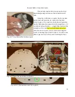
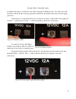
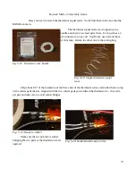
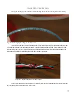
Strip about 1/2” of insulation off the red wire and set it in place on the middle of the square pad
with the “+” symbol next to it. (The “+” indicates that this is the Positive connection.)
You may need to use something to
hold the wire into place while you solder it. I
used a pair of wire cutters to weight it down.
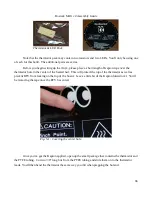
Now perform the same task with the black wire. The black wire will be soldered to the pad
marked with the “-” symbol. (The “-” symbol indicates that this is the Negative or Ground
connection.)
72
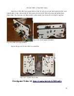
Fig. 5-18: Ready to solder.
Fig. 5-19: Soldered in place.
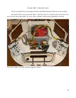
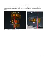
Fig. 5-20: Onyx power leads soldered into place.
Summary of Contents for Rostock MAX v2
Page 25: ...Rostock MAX v2 Assembly Guide Melamine Parts Sheet 1 25 ...
Page 26: ...Rostock MAX v2 Assembly Guide Melamine Parts Sheet 2 Melamine Parts Sheet 3 26 ...
Page 27: ...Rostock MAX v2 Assembly Guide Melamine Parts Sheet 4 27 ...
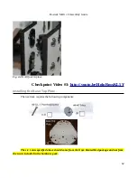
Page 171: ...Rostock MAX v2 Assembly Guide 171 Fig 14 8 Spool holder support installed ...


