Rostock MAX v2 Assembly Guide
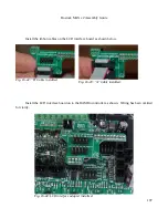
from the “stock” motors. Later on we'll be making a change to the firmware to account for this
difference.
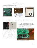
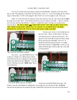
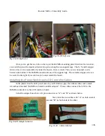
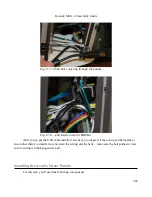
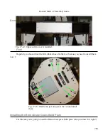
Finally, you'll need to plug the big power connector into the side of the RAMBo as shown
below.
Installing the RAMBo Into The Machine Base
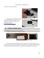
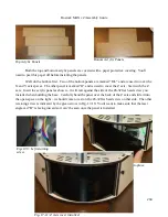
Now the RAMBo board can be installed into the base of the printer.
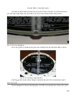
The RAMBo mounting plate has two curved tabs that fit into slots located on the top plate of
the base. When installed correctly, the tabs will fit into those notches and the base of the RAMBo
mount will rest on the two support legs that you installed when you were building the base.
195
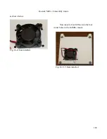
Fig. 16-36: Power connector attached.
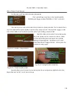
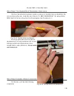
Fig. 16-37: RAMBo installed!
Summary of Contents for Rostock MAX v2
Page 25: ...Rostock MAX v2 Assembly Guide Melamine Parts Sheet 1 25 ...
Page 26: ...Rostock MAX v2 Assembly Guide Melamine Parts Sheet 2 Melamine Parts Sheet 3 26 ...
Page 27: ...Rostock MAX v2 Assembly Guide Melamine Parts Sheet 4 27 ...
Page 171: ...Rostock MAX v2 Assembly Guide 171 Fig 14 8 Spool holder support installed ...


