Rostock MAX v2 Assembly Guide
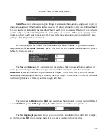
Interface Layers
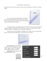
allows you to specify solid layers interspersed with the support material. This
comes in handy when using multiple extruders. For example, if you're printing a part in PLA with lots
of support, you can generate all the support with PLA, and then have 5 or 6 interface layers of PVA (a
water soluble filament). The print would then only be in contact with the PVA interface layers and it
would be a flat layer to print on. When finished you can dissolve away the interface layers and the rest
of the support falls off the part cleanly.
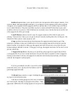
X and Y Distance
dictates how far away the support structure will be from the part you're
printing. You want it as close as you can get it without it actually touching the surface of the part. The
default of 0.7mm seems to work out pretty well.
Z Gap
specifies how many layers should separate the support material from the part. This
parameter contributes to how easy or difficult it is to remove support material from the part once the
print is finished. If you have too little gap, the support material will have more of a grip on the part
surface making it difficult to remove. If the gap is too large, the support material won't be able to do its
job very effectively.
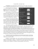
If
Support Everywhere
is checked, you're probably going to get more support material than
you bargained for. If you have an internal feature of a part, this may be required in order to support it,
but keep in mind that it will also add support to features like horizontally oriented holes, which don't
normally need support to print properly.
If you've got multiple extruders on your Orion, these
parameters allow you to specify which extruder is used for
generating support structure.
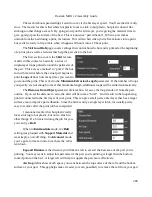
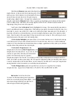
The
Repair
page contains a couple of settings the govern how (and if) the slicer will attempt
any repair of invalid part models.
Sometimes modeling programs will create a model that
isn't “water tight”, meaning it's got gaps in the surface. These
gaps make it difficult for the slicing engine to do its job and in
292
Summary of Contents for Rostock MAX v2
Page 25: ...Rostock MAX v2 Assembly Guide Melamine Parts Sheet 1 25 ...
Page 26: ...Rostock MAX v2 Assembly Guide Melamine Parts Sheet 2 Melamine Parts Sheet 3 26 ...
Page 27: ...Rostock MAX v2 Assembly Guide Melamine Parts Sheet 4 27 ...
Page 171: ...Rostock MAX v2 Assembly Guide 171 Fig 14 8 Spool holder support installed ...


