


Tel: 886.909 602 109 Email: [email protected]
79
A Wave Segment file with sample counts of 40,000 is to be generated according to the formula:
Sample Counts = Length of Wave Segment (Symbol) × Over Sample Count, where the Over
Sample Count is the number of interpolations of each symbol at the time of shaping filtering. The
software automatically calculates the Over Sample Count by default, whose maximum is 32; in the
current model 1465, each sampling point occupies 4 bytes (I channel data occupies 16 bits and Q
channel data occupies 16 bits), and the maximumstorage capacity of the baseband board is 4GByte
(8GByte option), so the maximum sample counts is 1GSample (2GSample option).
The software automatically limits the length of the input symbol and the value of the Over Sample
Count based on the current baseband storage capacity. It takes a long time to generate a Wave
Segment if the Over Sample Count is big. It is recommended to turn off automatic counting of the
Over Sample Count and set the Over Sample Count to 4.
In this example, the sample counts to be generated is 40000, the Over Sample Count is set to 4, and
the length of the Wave Segment (symbol) is set to 10000. The Samp Clock of the Wave Segment to
be generated is 4 MHz and Samp Clock = Over Sample Count × Symbol Rate; the symbol rate is set
to 4 Msps.
Step 6. Select the Data Source:
Rotate the RPG clockwise (or counterclockwise), move the focus to the “Data
Source” combo box, and press the knob to select PN9. Or touch the “ Data Source” option box on
the screen to select PN9.
Step 7. Set the Wave Segment modulation parameters:
The Modulation Type combo box displays the currently selected modulation type.Select the
Modulation Type QPSK; or touch the “Modulation Type” combo box on the screen to
successively select [PSK]—>[QPSK/OQPSK]—>[QPSK]. Select the default filter.
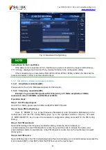
Step 8. Set the Wave Segment marker:
Select the “Edit Marker” button to open the Edit Marker dialog (Fig.3.12). In this dialog the user can
edit 4 independent markers.
The coordinate system length of the Edit Marker dialog box is 40000, the Sample Counts edited
previously. Select the marker with the mouse, double-click the left button at the specified index, and
set the output of the marker when the marker line is High or set no output of the marker when the
marker line is Low.
The example requires setting the markers at the start and end of the Wave Segment. Put the mouse
at the start of the marker 1 and double click the left button to set the marker line to High when the
current index is displayed as 0. Put the mouse at the index 100 and double click the left button to set
the marker line to Low. At this time, it is High from indexes 0 to 100 and it is Low from indexes 100 to
40000. Similarly, the marker line is set to High between indexes 39900 and 40000.
For easy selection of the marker index, the user can modify the value of the “Amplification
Range” item and then select the “Amplification” option. The coordinate scale is displayed
with the current index as a center based on the value of the Amplification Range after
modification.
Thus, during the playback of the Wave Segment, the marker 1 port outputs a high level
when the sampling points from 0 to 100 and from 39900 to 40000 are played. After the editing, click
the “Generate Marker File” button to generate example.mrk marker file in the wav folder and in the
same directory as the Wave Segment.