Tel: 886.909 602 109 Email: [email protected]
40
input/output
externally grounded.
31
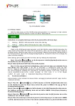
Trigger input
BNC female, TTL rising edge active, used for external trigger step and
frequency hopping in list sweep.
2.3 Basic configuration method
This section presents basic settings and configuration methods of the S1465 series signal
generator.
2.3.1 Description of basic settings
This section introduces the main features of UI and basic methods of configuration settings of
S1465 series siginal generator, which will be used in subsequent different configuration tasks.
2.3.3.1 Main features of operating interface
The front panel LED display is used for showing the UI which is a new-type visual GUI clearly
displaying the whole process of signal output. The operating interface is divided into different areas
according to the function modules and allows concurrent operation of multiple modules, display of
states, parameter settings and configuration results of all configuration tasks. This section focuses on
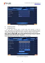
the composition and functions of UI. The operating interface is illustrated below (Fig.2.13) and
itemized in Table 2.7:
Fig.2.13 Operating Interface
Table 2.7 Display annotation item description
No.
Name
Description
1
Main information
area
It displays main parameter values: Frequency, amplitude, modulation
ON/OFF, RF ON/OFF and modulation state. It corresponds to the
frequency display, amplitude display, modulation switch and RF switch as
shown in Fig.2.13.
2
Function area
Clicking a function in this area by touching the screen or pressing a
function key on the front panel will display the corresponding menu in this
area. It corresponds to the function area as shown in Fig.2.13.
3
Status display
area
It displays the instrument operating mode and state, and the current latest
warning/error message. It corresponds to the status display and
modulation display as shown in Fig.2.13.


