


Tel: 886.909 602 109 Email: [email protected]
54
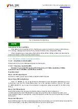
Now the modulation indication area in the main information display area shows
and
the text message area tabulates the component information of pulse modulation.
Fig.2.23 Setting of Pulse-modulated Signals
2.3.3 Description of main configuration scenarios
The function configuration modules of S1465 series signal generator correspond to their respective
configuration dialogs and centrally manage the relevant parameter information to facilitate parameter
setting and editing for specific functions.
2.3.3.1
Frequency
The Frequency Configuration Dialog is used for setting RF output frequency parameters
including: CW, frequency step, frequency offset, frequency reference, etc. To facilitate user input, the
selection order of CW input box is put in the first place among the selection orders of all controls in
the Frequency Configuration Dialog, that is, the CW input box is directly editable when the Frequency
Configuration Dialog is opened for the first time. Pressing the
【
Frequency
】
key on the front panel
or clicking the [Frequency] function area on the screen will display a pop-up Frequency Configuration
Dialog on UI, as shown below in Fig.2.24 and 2.25.
Fig.2.24 Frequency Configuration Dialog