Tel: 886.909 602 109 Email: [email protected]
50
NOTE
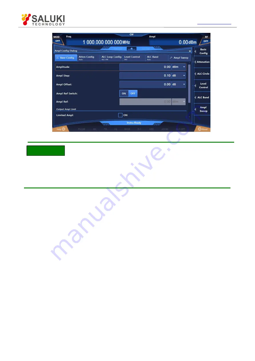
Fig.2.19 Power Level of 0dBm
Power level entered out of power setting range of the instrument
The power input box has a preset range of input and displays the upper and lower limits closest
to the input value. If a power level out of the range of fixed-amplitude power is entered, the status
display area will give a warning message indicating “Amplitude Not Fixed”.
4) Set amplitude reference and offset
When the amplitude reference is turned on, the power-related parameters are relative values
based on the currently set amplitude reference. For example: The frequency shown in the main
information display area is the difference between the RF output frequency and the frequency
reference.
Example: Set the power frequency to 10dBm and offset to 5dB.
Operation steps:
Step 1. Reset.
Press
【
Reset
】
to set the instrument to the manufacturer-specified state.
Step 2. Set the power to 0dBm.
Press the
【
Amplitude
】
key and turn the front panel RGP to select the Power input box or click the
[Power] function box on the screen to make it editable; enter the power value of 0dBm;
Step 3. Set the amplitude reference to 10dBm.
Edit the amplitude reference as 10dBm;
Clockwise (or counterclockwise) turn the front panel RPG to select Ampl Ref Switch, and turn on
the amplitude reference by pressing the knob or clicking Power Frequency ON on the screen.
Clockwise (or counterclockwise) turn the front panel RPG to select the Ampl Ref input box.
Press the knob to make the box editable; the amplitude reference currently shown in the box is the
system default or the value set during the last amplitude reference operation. Enter 10dBm and end
typing. Then the power shown in the main information display area is actual RF output power minus
the frequency reference -10dBm (RF output power (0dBm) – amplitude reference (10dBm)), and
Ampl Ref is turned on, as shown in Fig.2.20.
If the amplitude reference is turned off, the power shown in the main information display area is


